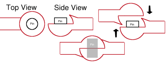
My basic hinge design
When working with my Perfect Grade Zaku, I realized there were a lot of things I wanted to change, among them, the hands. I wanted a round-finger look, but I didn't want to sacrifice the PG posability. This led me to find a way to build new hands and the mechanical parts I would need to make them be posable without sacrificing my goals for appearance.
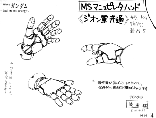
My first decision, after I abandoned the idea of merely altering the PG hands to approximate the look I wanted, was that these round-fingered hands should follow this design, the hand design used in Gundam 0080 for all the Zeonic mecha. It just happens to be my favorite round-fingered hand design: really, most other high-detail round-finger hands follow a similar design. The key to being able to construct these hands was finding a way to build the spherical knuckles which join adjacent cylindrical finger segments. Wave sells an option part which is similar in design to the knuckles, L-Joint 3: however, the PG Zaku fingers are about 4mm wide, and the L-Joints are around 7mm in diameter, so there was no way they would work for the finger knuckles. Additionally, there's a problem with the L-Joint 3 design I knew I'd have to overcome: the joint is made of two halves, which tend to separate from each other when the hinge is turned.
Another popular option for building these kinds of hands is to string spherical beads with stiff wire: however, from what I've heard this technique leads to hands of limited posability, and the wire will break if the hands are re-posed too many times. I decided I wanted to at least try to build actual durable hinge-hands before falling back to using wire-core or static hands.
In order to determine whether my plan to scratchbuild a 3mm version of Wave's L-Joint 3 was practical, I tried a series of prototypes based on resin copies of a 3mm ball joint cut in half lengthwise. At first the halves were joined with a .5mm thick steel pin, later 1mm flower wire was found to make a stronger hinge. The first prototype built around the flower wire hinge pin looked promising, but ultimately broke down. The current prototype hinges are being built with a steel pin reinforcing the pin socket in each hinge half as well as the shaft extending out from the hinge. The reinforcing steel pin seems to have a number of advantages:
Although the steel pin construction does help keep the joint together, really the hinge as constructed is only useful if it's installed in a way that the two halve cannot separate from one another. In this case, the hand design shows the finger segments covering up a lot of the knuckles, so the finger segments themselves apply force to keep the hinge halves together:

Once the hinges are assembled, they are permanently installed into the finger segments which surround them. Because the finger segments almost completely surround the knuckles, the hinge halves cannot separate unless they are first removed from both finger segments in which they're installed: and because they're installed permanently (with super glue, SGT, etc.) that's not much of a concern. Anything which could cause the knuckle halves to separate would almost certainly destroy the whole finger in the process.
So far the results are very promising. The finger looks good, it wasn't prohibitively hard to assemble, it has about the same level of joint friction as the original PG fingers, and so far the opposing stresses in the knuckles haven't torn the joints apart. There is certainly more refinement to be done before I'll be ready to build a whole hand: I need to streamline the process and refine the parts to get exactly the cosmetic appearance I want. All in all, however, it's been a very satisfying excercise, and I think it'll lead to more home-made option parts which meet my original criteria for this project: "Very small, cosmetically perfect hinges".