Hakuheisen status, controller board progress
By tetsujin on 2009-07-08 in Models
Tags: 1:72 Armored Core CR-C75 "Hakuheisen"
I’ve finally gotten back to work on my Armored Core “Hakuheisen”, hoping to finish it for Otakon. I think this is basically a reasonable goal at this point: most of the parts are paint-ready, the only hold-up is wiring for the LEDs that are being installed.
I’m not going to have the microcontroller board or its software ready for Otakon – and I don’t know if I’ll be lighting the thruster LEDs when it’s on display at the con – but I also don’t want my rush to finish the model for Otakon to compromise my goals for the model, so basically the lighting work is proceeding as planned, the only difference is that for any parts of the process I think might put my deadline in peril, I’m finding ways to work around those things such that I can return to the project later and complete things the way I intend.
So for the most part things like the microcontroller board are on hold: however, I was in Chicago for the last several days, so while there (and on the train rides to/from the city) it was impossible to do actual model work – so instead I revisited my “Raven” PCB design to try to improve it.
Upon revisiting the original version, based on the 12F683 microcontroller, I discovered that the thing was basically a mess. Of the four I/O lines actually allocated to LED control, one of these was input-only. There was no provision for in-line current-limiting resistors between the I/O pin and the microcontroller pin, but there were pull-up resistors on each I/O line (which basically makes no sense…)
Additionally, since I’ve been working on adding the LEDs to the model itself, I’ve had time to reflect upon the basic design of the controller board with respect to the LEDs it will be controlling: eight white LEDs for the thrusters (using up to 20mA each – though they run respectably on 10mA each) controlled by as many as two I/O lines, capable of supplying or sinking only as much as 25mA each. So to run those eight LEDs on two outputs from the 12F683 would limit me to about 6mA for each LED, unless I could run pairs of LEDs in series. This would leave no room for a current-limiting resistor, and make the LEDs rather sensitive to minor changes in supply voltage.
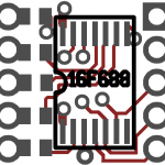
Thus, I’ve started over, using the 16F688 – a 14-pin device. The SSOP version is about the same size as the SOIC version of the 12F683. (That means it’s harder to solder, unfortunately – but a lot more I/O pins to work with.) The new board design currently offers five I/O pins with provision for current-limiting resistors in-line. Additionally, two more I/O pins are available via solder points on the board.
One design decision I’m not sure about at this point is my attempt to use the chip’s USART for synchronous I/O (possibly using the I2C protocol) – and sharing the serial I/O pins with the ICSP pins. Using the USART could be advantageous, if I can figure out how… Or, alternately, not using the USART could be advantageous, as it would free up two I/O pins. Tying the two pin pairs together has a few disadvantages as well: it becomes necessary to avoid driving the two pin pairs in conflict with one another, and it negates the possibility of using in-circuit debugging at the same time as the serial I/O. (I’ve never used ICD, so that bit doesn’t bother me much…) It may actually be worth bit-banging the I2C protocol using the same I/O lines as I use for ICSP just to free up more I/O lines.
Another issue is that, due to the very limited space on the board, there’s not much room for pin-through-hole components like the 2mm pin headers I use for external connections. If I switched to surface-mount connectors for these connections, it would complicate the problem of preparing the board for use, but it would probably allow me to provide more I/O lines, as well.
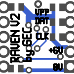
Also, if you look at the side of the board with the PIC on it – there’s the five I/O lines on the left (for LEDs) and the five-pin ICSP interface on the right (four lines of which are also used to power and control the board during operation) – but there’s no provision for power or ground connections to the LEDs. In the present design, those connections must be taken either from the ICSP header (I guess by soldering extra-long pins to the ICSP header and attaching connectors to both sides) or by sacrificing one of the I/O connections to turn it into a voltage or ground line. Again, this goes back to the basic problem of fitting through-hole connections onto a board this small.
One possibility I have considered is to design the board with sections that could be cut off if they’re not needed: so, for instance, an additional five I/O lines could be provided at the top of the board, increasing its size to 11mm x 12mm – but with a dotted line silked on, so the extra I/O pins could be cut off if the installation requires a smaller board.
This new design solves the problem of having more I/O lines, but it doesn’t solve the problem of driving a significantly higher number of LEDs. For that, I think I need a second board: some kind of LED driver, perhaps in combination with a voltage regulator and a higher voltage source for the models. This would allow me to run multiple white LEDs in series where necessary… I haven’t settled on a plan for this, just yet.


Post a Comment