AC Hakuheisen Wiring
By tetsujin on 2008-10-30 in Armored Core Group Build, Models
Tags: 1:72 Armored Core CR-C75 "Hakuheisen"
So this is the project I wanted to have done for the MMC Blue contest last month and the Armored Core group build this month. Unfortunately there’s no way I can meet the build deadline at this point: I spent too much time working on Granitecon projects this month and last.
Anyway, the project is mostly ready for paint: most all the seams, etc. have been dealt with, the various warpy surfaces have been sanded flat, etc. The big thing going on right now is I’m working on wiring for the thing: wires to drive the LEDs installed in the thrusters, plus wires to power and communicate with a microcontroller that will control the LEDs.
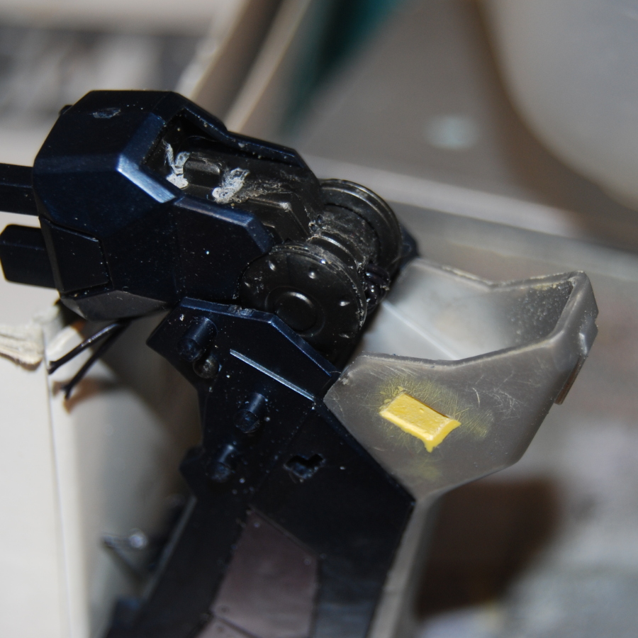
One thing I want to show people – maybe this will be of help to someone – is how I modularized the arm to simplify painting. Armored core kits built OOB don’t break down well for painting – but with a little bit of modification (and a willingness to super-glue the thing if necessary once it’s painted) the painting process can be simplified a lot. This is the kit’s forearm (CR-A71S2) – to simplify dealing with the silver parts I didn’t glue on the wrist part, and I trimmed down the silver parts so they could slide in after the rest of the forearm was assembled. The detail part at the back of the arm was also modified so it could slide out, rather than being trapped once the forearm is assembled.


The big thing that’s still going on with this project – and which is making it a little bit complicated, is the wiring. I already posted images of the head with LEDs installed – beyond that I want to light the thrusters, and install a microcontroller in the AC to control the lights. However, it wasn’t until very recently that I started giving thought to where this microcontroller would be installed. The legs would potentially offer the most space, though in practice there’s really a lot of junk in the interior of the leg filling up space… And what I slowly realized about this AC kit – and most of the others, for that matter, is that there’s really not much space at all inside. Parts like the CR-C98 or C01-GAEA are built up out of so many layers that when you strip them all off and get at the real interior, there’s nothing left. The CR-C84 has a similar predicament, except that it actually has a surprisingly large amount of space inside at the back end of the core… Also, in ACs, there’s a lot of bulky parts, but they’re usually very flat as well. It didn’t help matters that I’ve already sealed up the core part with glue, so it’d be pretty tough at this point to get at the interior.
I identified three places where I could attempt to store a microcontroller: the first, and most obvious place to stash something in any AC kit really, was in the belly. On most of the AC kits released so far, the bottom of the core part terminates in a sort of “bucket” which mounts the ball joint that hooks up with the hips. The whole part really serves no purpose except to fill space and provide structure, so on a lot of the cores released so far (incl. C75, C98, C84, GAEA, probably others) it is pretty much just a hollow bucket. The other two locations that seem promising as places to hide the microcontroller are in the back, near the Over-boost (the OB could be removed to access the circuit) or in the front of the chest (the silver part of the chest could be removed to access the circuit). So far I feel like the belly is still the best choice: the OB area is promising because the parts I’d have to remove to get access aren’t important to the structure of the robot – and because the parts back there remove so neatly, and could conceal a big gaping hole so neatly when assembled. But the belly is a more central location: I wouldn’t have to think too hard about how to route wires from the back thrusters, head, and legs to the back of the torso.
But the problem with installing a circuit there (as with most anywhere in this model) is that there’s not a lot of room for it. I hacked up the belly part pretty thoroughly to make more room (believe it or not, after all this damage the thing still looks perfectly normal when all’s assembled, due to all the layers of detail that go on outside) and still there’s barely enough space for a little PCB that’s 11mm x 15mm.
Because I’m wiring the thruster lights and running power and communications for a microcontroller in the belly, that means there’s gonna be five wires running up through the leg… I tried two different approaches to running the wires through the knee joint: the first was to drill holes just above the knee joint leading to a hidden area in the back of the leg. Wires going from the lower leg to the upper leg would be visible on the front side of the knee joint – maybe people would take ’em as detail or maybe they’d just look cheesy… I’m not sure. :D The second approach was to actually drill straight through the middle of the knee joint itself – this hides the wires very well, they’re only visible (just a bit) when the knee is almost at full flexion.


This led to another realization – it would be exceedingly difficult at this point to install one of the microcontrollers I commonly use these days – the 16F628 – or any part with a similar number of I/O lines. The part itself is available in sizes that would fit in the space – but when you add in resistors and wires and connectors and such, space starts to run out fast. Plus wiring all that without a board is a real pain – I’ve done it before and I’d prefer not to do it again.
The board I used to trial-fit inside the belly is a Sparkfun SOIC-8 breakout board… Initially I thought using that board might be a good, cheap, low-effort way to wire up an 8-pin PIC inside the model, since I wasn’t feeling too confident that I’d be able to get an 18-pin part in there… However, I decided that the breakout board didn’t provide enough features for the amount of space it uses. My final circuit will need current-limiting resistors on all the LEDs, plus pull-ups on the communication lines, multiple connections to the ground line, etc. – so I took a crack at designing a microcontroller board that would fit in the C75’s belly, host a SOIC-8-sized Microcontroller, give me all the connections I needed, and also hold a bunch of surface-mount resistors for the pull-ups and such. It was a real tight squeeze – I’m not actually sure if some of the traces might be too close to the board edge. But I think if I get it made it could be real handy. I may try etching it myself. Trying to drill all those holes will sure be fun… :D
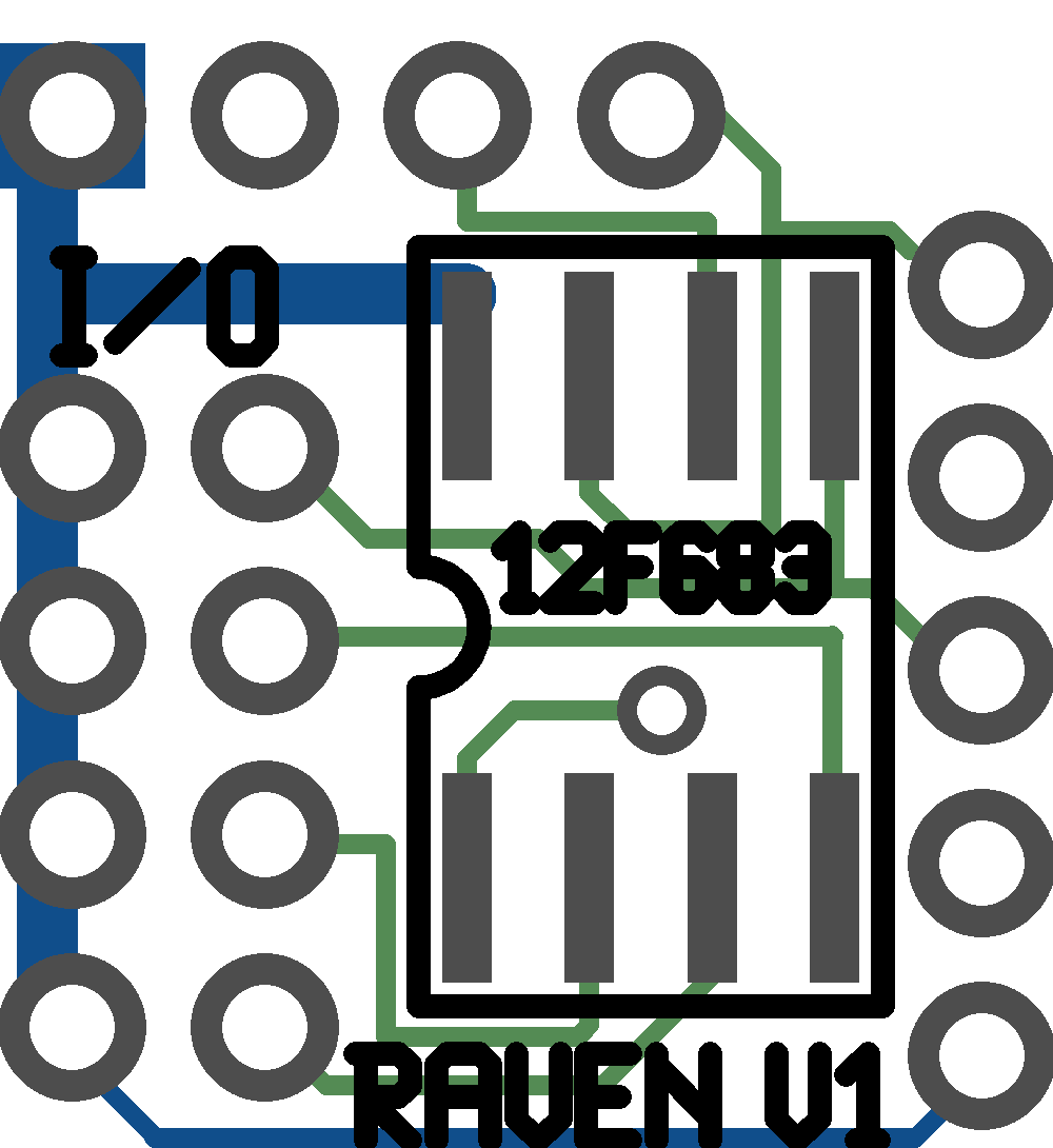

In retrospect I’m not sure I need both ICSP and PWR/IO as separate ports, since the ICSP port provides all the same connections as PWR/IO but just includes an extra one. I’m thinking of redesigning the board to unify those two ports, and hopefully make the board a little smaller in the process. I figure if I need to connect those pins to more than one external port, I can just run long pins through the board holes, and connect socket headers on both the top and bottom side. But I’m also thinking of making the board longer but narrower – and possibly also better suited to the use of right-hand pin connections – so I may make some changes to the board layout before I try actually making one.
Post a Comment