Micro USB power connector for Nintendo 3DS
By tetsujin on 2016-08-21 in electronics
Tags: 3DS, console modding, electronics, video games
I bought a 3DS recently, and I’ve had a lot of fun with it. But when I bought it, I was kind of shocked to learn it is sold without a charger. How can people be expected to continue to use their new portable game system after the first few hours of use without the means to recharge its battery?
The answer, of course, is that the proliferation of USB as a power port for small devices has rendered dedicated chargers largely obsolete. However, the system itself doesn’t have a USB connector: it has a proprietary connector. In a sense this isn’t a significant issue: third-party USB charging cables for the system are inexpensive online.
However, I did get a bit fed up with the situation: When I misplaced my charging cable, I couldn’t use the system. And if I took the system on a trip and forgot the cable, my opportunities to buy a replacement would be limited, and expensive. My phone, on the other hand, uses Micro USB cables. I can buy those for a few bucks at a gas station if I have to, and they’ll usually be among the cables supplied at charging stations. I love that convenience. So I decided to replace the system’s proprietary power connector with a Micro USB connector.
The first step in the project was to design a printed circuit board to hold the Micro USB connector. A power connector needs to be well-anchored, and small components like these are much easier to mount and hook up if there’s a PCB. I use a package called Kicad for my PCB designs, and it had been a while since I’d used it, and it took some effort to get back up to speed, but I put together a design I was pretty confident in and had some prototypes made. For the prototypes I used a service called OSH Park. From my measurements inside the 3DS I determined that I’d need a 1mm thick PCB rather than the usual, thicker boards. This meant I’d have to wait longer for my boards to be made, but the result would be worth it. I ordered the boards at the end of July for under a dollar, and received them three weeks later.
To prepare the board for installation, I had to solder the micro USB connector to it. This is a bit challenging without a reflow oven, as both the PCB and the connector are very small and it’s hard to get access to the areas that must be soldered when everything is in place. With the USB connector mounted, I ran some tests to make sure the connections were good and nothing was short-circuited, then I soldered some pins in to connect the power board to the 3DS main board.
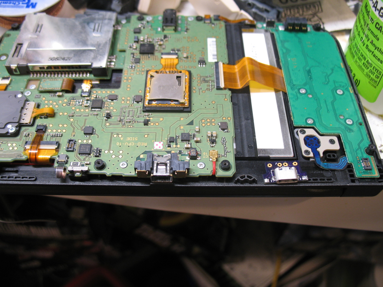


Perhaps the biggest challenge (and risk) in the project is removing the main board from the case. The main board is connected to other parts of the system by about 12 cables, and if you’re too rough with them, they’ll break. This is especially risky with the display cables, which are looped through the system’s hinge and three of them connect to one corner of the board without a lot of extra slack. It’s all too easy to damage these cables and wreck the system.
When the main board was removed, the power connector was desoldered with solder wick, and the power board was mounted to the main board, secured by the same solder points originally used for the old power connector. At this point, the USB power connector was good to go, but I wanted to improve a few details.
On either side of the power connector, the 3DS has two exposed metal tabs: these are used to charge the system in cradle accessories: just drop the system in, and the cradle will make contact with the tabs and charge the system. I wasn’t sure I needed to retain this feature, because I don’t have a charging cradle, or any plans to get one, but leaving them out would result in two open holes in the system case, so I decided to retain them.

The metal tabs were separated from the old power connector, and a piece was cut off to prevent them from touching the USB connector and shorting out the power supply. Placing these proved difficult: originally they were held in place by the old power connector’s plastic frame. When re-installed they would be soldered to the main board and to an exposed pad I included in the power board’s design, but getting them properly aligned while soldering them proved difficult.
After installing the tabs, I did some more testing to ensure everything was connected correctly and nothing was shorted. (This is important, as a short could wind up damaging the system when it’s turned on.) However, it seemed I had discovered a problem: a test with a meter showed an electrical short between the power pins. I really didn’t want to pull everything apart after having just installed it, so I tried to find the problem and identify a solution. After reviewing the power board design, I thought I’d found it: it appeared that the exposed pad for the cradle’s positive terminal was connected to one of the ground pins on the power board. Convinced that I’d found an error in my design, I hacked away a small piece of the 3DS main board to get access to the offending trace and sever it.


On further review, it seems this flaw in the board design wasn’t a flaw at all, and the trace should have been left as it was. The apparent short shown by the meter was in fact the 3DS main board consuming the power the meter was using to detect continuity. Cutting the trace did no harm, since the trace connected two things that were connected on the 3DS main board anyway – and it serves as an example of how things can be reworked without a full teardown.
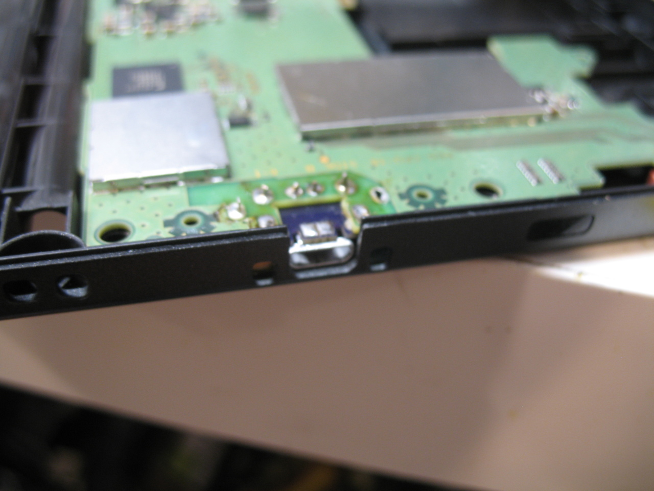
Finally, I was ready to close up the system and put it through its paces. I was afraid I might have damaged the system in the process of working with it, but it seems to have come through without any problems. Because the Micro USB power connector is a bit smaller than the original 3DS power connector, I filled some of the extra space with foam mounting tape.

I’m very pleased with the result: now I can charge the system with any standard Micro USB charging cable. I love knowing that I don’t need to bring a special cable with me to keep the thing charged. I can use the same cables I use to charge my phone, and if I’m ever in a situaton where I don’t have a cable, I can get one. The gap around the smaller connector is a little unfortunate, and I still hope to devise a better way of filling that gap to prevent debris from entering the system there. I may do this to some of my other portable systems in the future: it can be a hassle finding my chargers for the Game Boy Micro, Advance SP, or DS Lite (all of which use different connectors) so it’d be convenient to have them all use a single, standard connector.
On the other hand, Micro USB may be supplanted in a few years by the new USB C connector. That new connector is influenced by the user-friendly design of the Lightning connector used on Apple’s iPhone. Among other things, this means it’s reversible: unlike Micro USB, in which you have to have the plug turned to one specific orientation to plug it in, with Lightning or USB C you can plug in the connector right-side up or upside-down and either way it just works. But at present I feel the C connector isn’t yet common enough to be worth using for something like this. It’s also a bit larger than Micro USB, which means I’d have to alter the plastic casing of the 3DS to use it.
If you’d like to try this mod yourself, my board design can be ordered from OSH Park. The board must be paired with a “top-mount” Micro USB connector. (I selected a “top mount” connector because mounting the connector that way fit the existing contours of the case better – you can’t replace it with the more typical “bottom-mount” connector, because that would reverse the polarity of the power connection, which would be bad.) I used this one by Molex. Just be careful if you do: it’s all too easy to wreck these portable systems when disassembling or reassembling them. If you’re not confident in your ability to do the job right, find an experienced console modder to do it for you.
Wow, thanks man! I just put in an order for my own set of boards. $1.90 with the faster manufacturing option. That and a couple dollars for a whole lots of USB ports should do me just fine. And it’s still cheaper than a single 3DS -> USB adapter!
Pat | 2017-01-26 | Reply
Nice! Glad you found it useful!
Just be careful if you’re not experienced with this kind of mod. On my first attempt at this kind of mod to a New 3DS-XL (prior to designing the PCB and all that) I trashed the display cable just in the process of opening the system. Then later while testing the mod I connected the battery wrong (I was trying to test things with the casing removed) and fried the charging circuit. I wound up buying another 3DS to replace it. I offer this mod design with no warranties, express or implied.
Hopefully, all will go well for you. …Or hopefully it already has gone well for you, since you posted your comment like two weeks ago and I didn’t see it… I’d love to see how it turns out once you’ve installed it. My modded system continues to serve me well – I absolutely love not needing a specialized cable for it.
tetsujin | 2017-02-15 | Reply
Hi
I just found this blog, it seems cool and you do some great job with your mods. I also like your models, since Im kinda into that but still trying my way in it.
I will give myself a try on this kind of mod, sice I have an Old 3ds Lying around with a faulty charging port, and it’d be fun to revive it again with a new port.
Greetings from Colombia!
Jhon | 2020-09-01 | Reply
Hi, thanks. Glad you enjoyed my work. I definitely enjoyed having a standard USB connector for my 3DS, though I had a lot of trouble with the mod work – I actually killed my first “New” 3DS XL attempting an early version of this mod, and the second unit I got to replace it failed when my kid tugged too hard on the USB cord. So just be aware if you try this – it’s kind of hard in my opinion.
This mod was designed for the 2015 model (the “New” 3DS XL) – so if you attempt it I’m not sure if it’ll work with other models. Also if you try it be sure to get the right connector. The mod is designed for an inverted micro USB connector, which is a little unusual, but using that connector allowed me to have the port right-side-up on the finished unit. (These days I’d go for a USB-C connector, but when I did the work I didn’t have anything that used USB-C yet)
I’m looking to get back to the model work, kind of been doing less of that in recent years, and then a few years back I had flooding in my basement workspace and I still haven’t got my new space entirely set up yet. Kind of frustrating…
tetsujin | 2020-09-01 | Reply