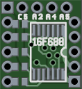
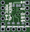
My first circuit boards! There’s good news, and bad news…
By tetsujin on 2009-11-16 in Models
Tags: 1:72 Armored Core CR-C75 "Hakuheisen", electronics, microcontrollers
When I got started on my recent Armored Core project I decided I not only wanted it lit, I wanted to light the head and all the thrusters… Not only did I want ’em lit, I wanted to be able to control the brightness, too. And not only control the brightness, but control them via an interface to the PC… And not only that, but I wanted this control system to support the connection and automatic control of many models’ lights, all at once… Needless to say it’s been a slightly complicated endeavour. At least, for me. I’m sure someone else could do it quite easily.
The trick is, the one place on this kit where it’s really easy to install a circuit board in this kit and be able to access it later is the belly – and there’s not much space there. If you cut out some of the excess material you can get a space about 10mm wide and maybe 13mm long in the belly. It would be possible to get more space up in the torso, but it would mean gutting the area in question, and then possibly rebuilding the area to give it structure again… And while the torso seems quite large, the problem there is it’s very very flat. Short of cutting up the torso (for instance, something similar to all the cockpit mods you can see on AC Armory) it would be very difficult, in my opinion, to install a circuit board in the AC’s chest, especially if you need to be able to get at it…
So my solution to this problem was to design a circuit board for projects like these – a board just about as small as I could manage, but incorporating as many features useful to controlling and lighting a model as I could manage. Today, after a couple weeks of waiting, I finally got the boards back from BatchPCB, the fabrication service I used… There is good news and there is bad news…


Are you wondering why I would need a special circuit board to be able to fit this circuit in my model? Basically despite this being a fairly good-sized model (around 15cm tall, humanoid, reasonably bulky) the kit is generally rather dense – and for maintenance reasons I needed a central location. Really the only options were the chest or the belly, and I went with the belly. Using regular pin-through-hole parts wouldn’t have been totally impractical, but it would have been very tough. As it is, I think it’ll be rather challenging to make the connections to this thing and put everything together nicely…


First, the good news. I ordered four 1″ x 1″ boards (each of which includes four 12mm x 12mm “Raven” boards) – and I got eight. This happens sometimes, I understand, because BatchPCB works by bundling a whole bunch of orders together into one big panel, then cutting up the big panel to get the individual boards people ordered… If something goes wrong with a part of that panel, they’ll re-do the panel… But when they cut up the panels into the individual boards, they’ll actually ship out both copies of your order… So it seems likely that part of someone else’s order was defective, and I lucked out and got an extra set of boards as a free bonus as a result.
The bad news: I screwed up. I’ve found at least three mistakes in my design. I can work around the mistakes, but it’s still kind of a shame because the whole point of making a board like this is to minimize the amount of work I have to do to stick a microcontroller into a model – but since I screwed up, some of that work gets added back in. The first mistake was that I got the power connections backwards! My second mistake was I was careless about how I organized the different I/O pins – The five I/O pins on the left side of the board are (from bottom to top) C3, C2, C1, A4, and A5… The four I/O pins at the top include C0, C4, A1, and A2… This could be awkward when I write the code that will run on the PIC itself…
The last mistake was that I’d meant for the header at the right of the board (the one marked with “0V, 5V, CLK, DAT, VPP” on the back side of the board) to double as an ICSP header for when I had to program the PIC… Unfortunately, I screwed up here – I tied these instead to the clock and data lines for the PIC’s “synchronous serial port” feature… This was a mistake I kind of derived from an earlier version of the design, in which the two pairs of clock and data lines were simply tied together so I could use one port both for programming and for runtime control… Using the SSP pins for the runtime control actually has some advantages, because the PIC includes real hardware support for the kind of interfacing I’ll be doing… To use the same clock/data lines as ICSP means that I’ve got to do all that in software. It’s workable but not ideal. On the other hand, it does mean that the SSP pins are left free in case the controller itself needs to use them to drive other circuits…
What this all means is I’m going to have to connect power to this thing opposite of how the writing on the board says I should… I have to omit the pull-up resistor for the reset line (despite having included a place for it on the back side of the board), and I either need to write firmware for these boards that will communicate using the SSP feature, or else I need to hook up to the ICSP I/O lines located on the removable section of the board… The problems surrounding the location of the individual data lines isn’t a huge problem, except that in projects where space is particularly limited (such as this AC project) I’ll be removing the optional section of the board to save space – that means I’ll mainly have access to three I/O pins from Port-C and two from Port-A… Writing to the pins on Port-A is going to require special care if I write the serial communication code myself (using the same pins as for ICSP), lest I accidentally overwrite some attempt at communication…
I’ve already worked out a “version 4” of the design that corrects all these problems – and it’s 1mm narrower, too – but getting the new design fabricated will require more money and another couple weeks… I feel like I’d best think about what I can do to make the new design even better – perhaps I could make the new version 10mm wide but longer… So it could still be cut down if it had to be smaller, but it could maybe fit in the Armored Core’s belly without cutting down the board first…


Post a Comment