Infrared Sonic Screwdriver
By tetsujin on 2011-02-02 in electronics
Tags: doctor who, electronics, microcontrollers, sonic screwdriver
I built this about a year ago for a friend who was getting his PhD. It’s the 9th/10th Doctor’s sonic screwdriver from Doctor Who. I added an infrared remote control circuit to it (based on the Lady Ada version of TV-B-Gone), multiple UV LEDs in a random flashing pattern, then sealed the thing up and gave it a nice paint job to cover up the seam lines.

I think projects like this are kind of popular among Doctor Who fans: after all, the sonic screwdriver is supposed to be able to do just about anything… That’s a tall order, obviously, but making it do something is a start. IR is nice, low-hanging fruit: you’ve got all kinds of devices out there in the world that will do what you tell them if you just send them the right IR code – no authentication or anything. The parts are cheap, the circuit is small, and it doesn’t take a lot of power to get a decent signal out. I’d love to do another one sometime with more functionality to it, but that’ll have to wait…
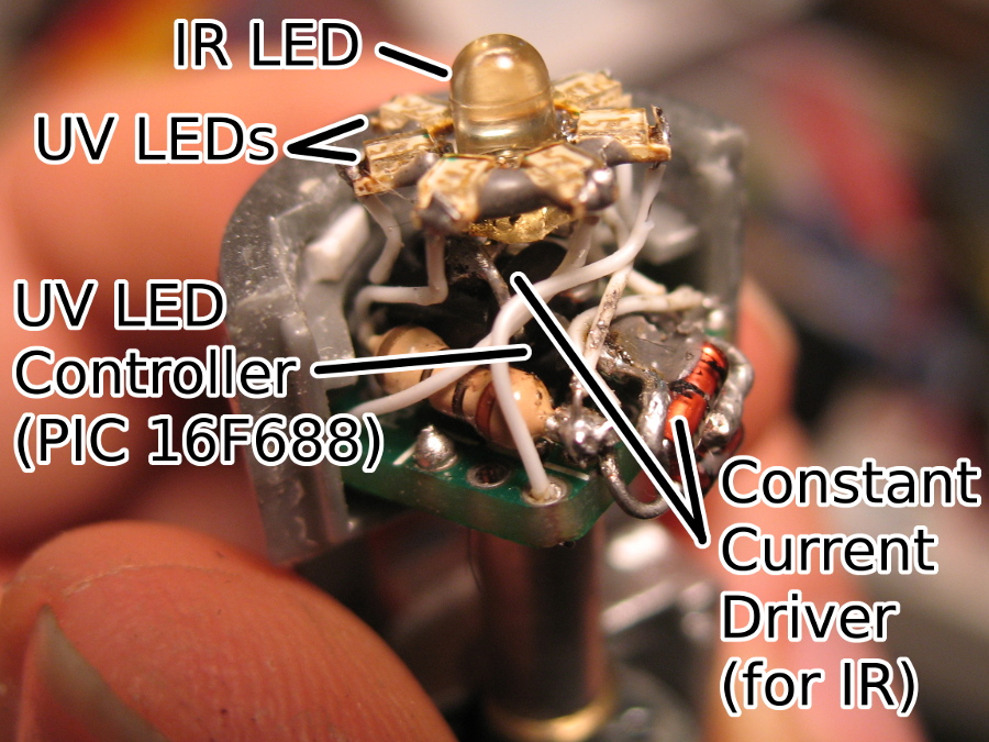
The circuit has two parts: the “light show” which drives the seven UV LEDs, and the IR controller which sends codes to turn TVs on or off. The light show is based on my Raven board: I had plenty of these kicking around so all I really had to do was solder a chip on, program it, and wire it to the LEDs. (Well, I also had to trim down the board to fit in the tight space at the head of the screwdriver…) I tried to work out a way to have that board send the remote control codes as well, but there was no way that was gonna work. The thing is, my Raven board is based around a PIC microcontroller, the 16F688 and its pin-compatible relatives. I chose that particular type of PIC because it’s available in a small size with a good number of I/O lines – they’re not terribly powerful otherwise. These chips would have been perfectly adequate for sending the IR codes, but they lacked sufficient storage to hold the data table containing the IR codes. Part of it is an architectural problem with the 16F-series PICs: the only way to store a data table on the chips is to store it as program code, a bunch of 14-bit instruction words, each containing 8 bytes of data. (The AVR microcontrollers, on the other hand, use a 16-bit instruction word, and you can use that to store two bytes of data if you need to store a data table in program memory… The PIC 18F family has that as well.) I made some attempts to compile the program with a smaller version of the data table and squeeze something useful on to the PIC: but it became clear to me that it was going to be too much work, for too little yield. I didn’t want to have to fabricate a new PCB for an AVR that could drive both the IR and the light show, so I went with two circuits instead.
The “Light Show” consists of seven UV LEDs arranged radially around the IR LED in the center. It was hell to put together, but once assembled and epoxied it was quite reliable. The light show sequence picks a LED at random every once in a while and boosts its light level up to some value 50% or greater, and then the LED fades out until it gets boosted again. The sequence is random but every once in a while, by chance or something, it winds up looking like it’s spinning one way or the other. I think the effect turned out a lot nicer than if I’d just produced a spinning sequence or something. It was important to have the light show controller close to the LEDs due to the relatively large number of connections to the LEDs there – that simplified the wiring and allowed me to treat the whole front-end circuit (LEDs plus light-show controller) as a unit.
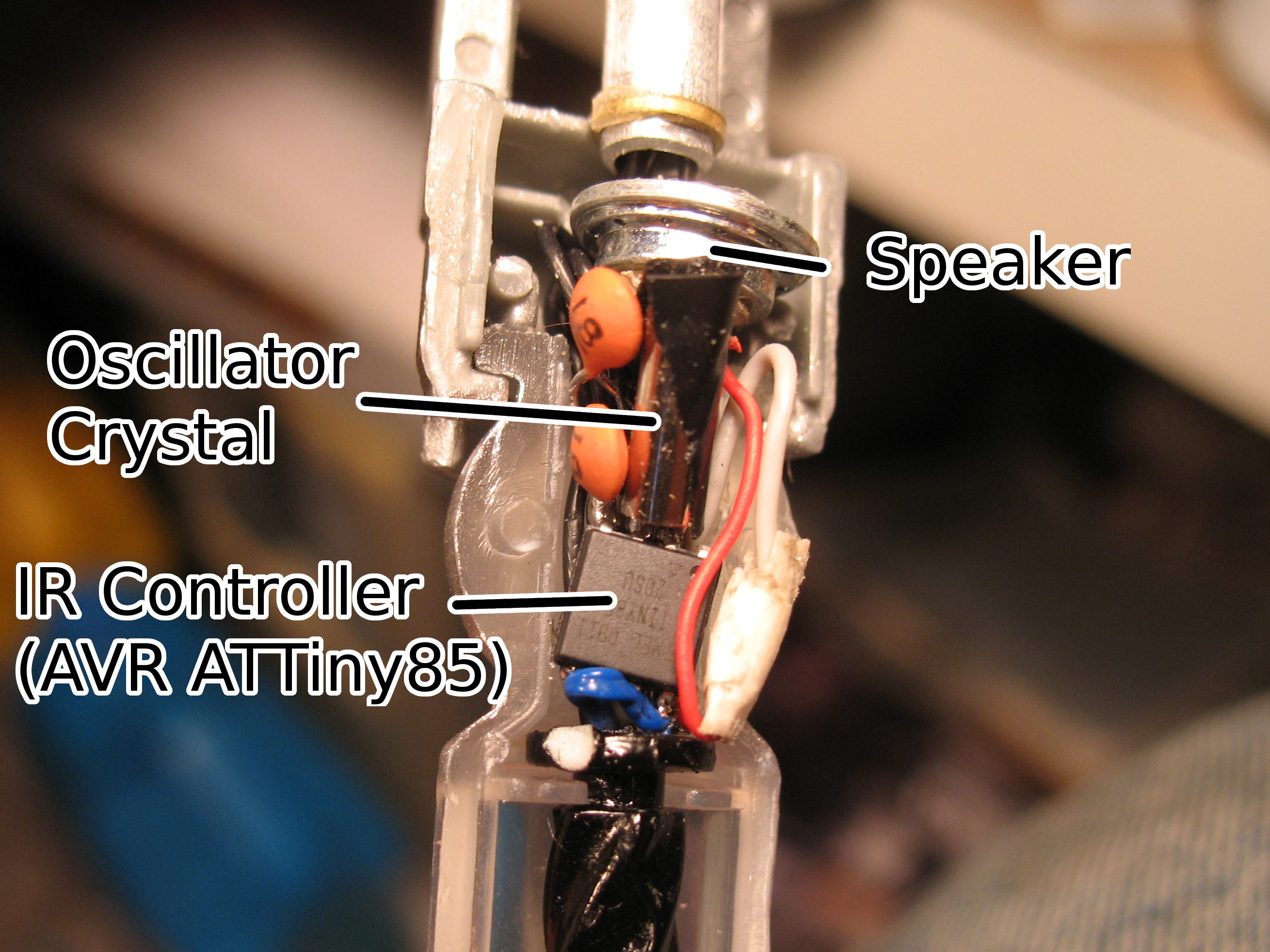
The IR circuit got stuffed into the neck of the screwdriver – the spherical section just behind the head. I cut out a little bit of extra space inside there, and the circuit was stuffed inside each time I reassembled it. The IR circuit is pretty small and pretty simple: the ATTiny85 is an 8-pin chip, and at SOIC size that’s about 6mmx6mm. The only connections it needed were power, a connection to the IR LED, and a crystal for the oscillator. When I was testing the breadboard version of the circuit I actually tried the ATTiny without the crystal (and set to use its internal clock source) – it seemed to work… Though I only tested it with my own TV. Microcontrollers’ internal clock sources aren’t super-precise, so I decided to play it safe and go with the crystal.
It was kind of a frustrating project: the IR circuit is wired up without a circuit board, which meant that the connections were prone to breakage. At one point I even broke a connection after the screwdriver was reassembled and repainted: I had to tear the thing apart to fix it – and in the process of fixing it other things broke, and I wound up rebuilding the whole circuit plus redoing the paint job. I brought the finished screwdriver with me to Tekkoshocon: I didn’t have a good opportunity to show off the IR feature, unfortunately.
I also had some reliability issues: sometimes the IR circuit wouldn’t do its thing. My first guess was that the IR LED was drawing too much power, causing the battery voltage to drop and the AVR to go into brownout mode. (That’d be a pretty significant drop – the AVR can operate on 3V, and the supply was 3 x LR44 cells, for a nominal total of 4.5V…) To try and solve the problem, I added a hefty capacitor and a fourth cell to the power supply and a constant-current driver to the IR LED – I don’t know for sure exactly what caused the problem, but that seemed to clear it up. Actually, though, my current best guess is that the reason the thing was going wrong is because I was foolish enough to gate my power supply for the microcontrollers through the pushbutton, rather than giving them a direct connection to the battery and using the switch as an input to bring the microcontrollers in and out of sleep mode. I had thought that this would help save power, or something – but the pushbutton really isn’t made to carry power: small changes in pressure or the angle of depression can change the thing’s resistance. I think that may have been causing the brownouts. Anyway, next time I build one of these I need to spend more time in the prototyping stage, and power the breadboard version with the same batteries that’ll be used in the final version – and no more last-minute design changes…
I am planning to build a second one: this time around I’m going to use one AVR microcontroller for both the light show and the IR function. I’ll have to come up with a circuit board design for the microcontroller and possibly one to hold the LEDs themselves. This means more planning up-front: I can’t take advantage of the Raven boards for an AVR circuit, and before I can design the board I need to prototype the circuit again to figure out exactly what needs to be on it… Plus the AVR in question will likely be a surface-mount package with no leads, meaning that I’ll need to use a reflow method to solder it on… But if I can work with that, installing the circuit into the screwdriver should be a snap. I could probably even avoid disassembling the neck.
I made a video demonstrating the screwdriver in action – I think before I make any more videos I need to think about how to present myself better. :)
Hei…nice to see your internal build online – just surfing and came across it.
If you manage to get the soic version with internal clock to work, I might likely be interested in one if you have an extra. I don’t think I’d be able to do any reflow for any smaller such micro anyhow.
sjason | 2011-02-02 | Reply
Well, the IR circuit -can- work on its internal clock – at least as far as I can tell with my limited testing. I had heard that the internal clock wasn’t precise enough – and that is a possibility (could be some TVs are more selective than others…) – but also the internal clock is more sensitive to changes in temperature or supply voltage – which could be an issue with such a small battery. I didn’t want to deal with one more possible reason the thing could fail, which is why I went with the crystal.
I don’t have any extras – it was a lot of work just to make the one. I am planning to make at least one or two more: this time around I’ll be streamlining the electronics, so that will be a lot easier. But there’s still the basic challenge of tearing the screwdriver apart, then patching it up again and repainting it… That’s a significant amount of work…
The thing with the 8-pin SOIC is that it’s quite adequate to run the IR, but it hasn’t got enough I/O pins to run the IR -and- the 7-LED light show. So the ATTiny85 could be adequate on its own if the UV LEDs were set up in a less fancy way – but I want the second one to be better than the first, not worse… And I can’t do the two-microcontroller thing again, ’cause I don’t want to have everything on PCBs. Wiring up the ’85 without a board made the circuit too fragile for my tastes.
There are tailed versions of the ATMega series that would be easy enough to solder by hand – the problem is they take up a lot of space. In the head of the screwdriver there’s, I think, about 11mm diameter to work with? Those surface-mount ATMegas also have a grounding pad underneath – which means hand-soldering is a bit of a problem, and the chip effectively takes up even more space because that grounding pad limits how much of the board space you can use on the opposite side… So I think I really am going to have to go with the smallest one I can get that has enough I/O pins to do the job (and enough ROM for the IR code table) – which means it’s going to have to be reflow. I’m not set up for reflow either, but I’ve heard it can be done with toaster ovens and hotplates and such, so hopefully I can make it work.
It’s a bit early to think much about selling IR screwdrivers – I’d consider it but I haven’t even started designing the second one yet…
tetsujin | 2011-02-03 | Reply
heh, well, as for buying/selling, I was tired when writing last also – so, rather for clarification, I meant I just need the tvbgone chip. I fully intend to have my own sonic machined from metal at some point – so just lining up what electronics I could possibly fit into it as such.
I’ve begun learning on pics, but find that there is only really anything for tvbgone for the atmels. I may at some point make an order for programmer and chips for atmels though, I guess…
Yet, also, I did afterward, notice a mini or micro tvbgone someone made with an 8pin soic, that had a tiny crystal – just haven’t figured out where to get such as yet – I have only the crystals that are four times the size of the chip, hehe.
sjason | 2011-02-03 | Reply
I learned on PICs as well, but have started into AVRs. The fact that there’s a version of GCC that targets the AVR is a huge bonus in my book. I still use PICs a lot, though, because I have those little PCBs that I designed around the PIC 16F688 – and because there’s not much in the way of AVR micros that have a comparable number of I/O pins and takes a comparably small amount of board space. But it’d be the same story if I were to look at the PIC 18F series…
The crystal I used in this thing was something like 3mm diameter and 10mm long. I bought it at Mouser. I believe there’s surface mount crystals that could be used as well, so I’ll have to look into that and plan the board accordingly.
8MHz crystal
If you do get a metal sonic I’ll be totally jealous. I’d love to have one but I’m not up for buying one and not really up to making one or having one made or whatever at present. That’s OK though, it’s a fun thing but in the end it’s just a thing. Sonic Screwdrivers are cool (and bowties, bowites are also cool) but I think Zakus are cooler. Sometimes it’s important to stay focused on those things that interest me most.
Once I do make the second version I’ll probably share the code and board design, and if you need one soldered up and programmed it could be a possibility – but I don’t want to get ahead of myself – it’s a board that doesn’t exist yet. :)
tetsujin | 2011-02-03 | Reply
heh, had to look up Zakus…
I like mouser also – cheapest on most micros that I’ve found so far.
Heh, yeah, I don’t want to just buy such as a metal sonic already on the market…will likely have to design my own sonic of sorts, perhaps – because not sure anyone can or will make one for me with the required spaces and voids for the parts I want to include.
Though yes, building a ‘functional’ sonic, has become too much of an obsession for me, so I want to get it completed so that I can move on to something else, haha…
As for programming – I’ve been working with C, because assembly just overwhelms me from the start.
sjason | 2011-02-04 | Reply
btw…wondering…what would you think about a bit of a programming challenge? heh, things are going too slow for me perhaps, and I sorta want this aspect wrapped up in a sense. Email me, and we can figure out details, and compensation, if so.
sjason | 2011-02-05 | Reply
Don’t know if I’d be up for such a thing right now. Don’t have a lot of free time at present and I’m trying to get projects ready for Otakon, when I can…
tetsujin | 2011-02-17 | Reply
This is awesome. I found this while looking up pictures of the old sonic screwdrivers for inspiration on the design of the same sort of thing you’ve got here.
I’m hoping to use a CREE IR LED, a basic 5mm UV LED, a white CREE and a laser pointer.
Probably not all going to come out of the same end, and with my limited understanding of electronics, may need to run it off of multiple power sources. It’s being designed as a multi spectrum flashlight first, a sonic screwdriver second.
This one will be for my girlfriend. I intend on making my own using the 200mw laser pointer I have.
I very much like your idea of using this to control TVs. Especially since I hear these IR CREE lights can do so from 100 yards away.
The problems I’m running in to in design is that the IR wants to be run off of 1.5V at 300mA I think? But all the constant current drivers I can find are meant for white CREEs at least twice as powerful. One suggestion was to use two IRs in sequence to use up the extra power. Once I know a bit more I might be able to rig up my own driver. But I’ve only been studying electronics this seriously for a week.
Good work! Keep it up!
Moonrabbit | 2011-03-08 | Reply
Going for a high-current IR LED sounds like fun… I’d love to try that at some point.
It’s possible you may not even need the constant-current driver. Since the IR signal is always pulsing, it may be enough to simply drive it with a transistor (the microcontroller I/O line wouldn’t feed it enough current…) – depending on how big a battery you’ve got attached, it might still even be within specs for the device (peak current at 50% duty cycle)…
tetsujin | 2011-04-04 | Reply
Hello,
I’m impressed by your work here. I’m an amateur in a great many things and have succeeded in creating a high quality steel sonic screwdriver. I’ve also succeeded in a few small electronic endeavours, but would like to take on the task of fitting IR remotes, circuit boards into my Sonic.
Where do you suggest I start in learning how to design microcontrollers (assuming I have a well-rounded background)?
Also, I would like to design a Sonic that can have multiple settings by sliding the middle button (default = 1, slide up one notch = setting 2, etc). Where would you suggest I start in this design?
Cheers,
Zach
Zach Summers | 2011-07-20 | Reply
Where to learn microcontrollers… That’s kind of a tough question for me to answer…
My remote control code was taken from the Lady Ada site, where it was generously made available for others to use. So that’s a good place to learn about the TV-B-Gone code. Coding for AVR micros is pretty easy, usually it’s done in C. You could start by learning Arduino – there’s a lot of good resources, but the main issue there is that to fit things into a Sonic you may need to make custom circuit boards to fit the space, and so there is a limit to how far you can go with Arduino for something like this, I think. Sparkfun is a good shop and also a good resource, so that’s probably a good place to pick up info as well.
As for the last question – it sounds like you want the micro on the sonic to know how far the Sonic is extended? (Did I understand correctly?) You could probably do that by putting a resistive strip down the edge of the sliding section, and putting a metal contact on the inside of the outer casing so that as the sliding section moves, the resistance changes… But building a working electronic mechanism like that in such a way that it’s reliable and durable can be tough. Another possibility would be to put a long linear potentiometer (like a volume slider, the kind used on mixer boards) on the sliding section, and make the slider stay put relative to the outer casing. But a slider long enough for the job would probably be pretty bulky – you’d eat up half your free space in the sliding section on that one trick…
Yet another possibility would be to use a photo-interruptor, kind of like what computer mice commonly used back when they still had mouse balls inside. The idea is that there’s an IR emitter right next to an IR detector (or two) and something interrupts the path of the light as you extend or retract the screwdriver. (Most likely the emitter/detector pair would be on the sliding section, while the interruptors would be mounted on the housing interior) – then the micro could count the pulses to see how far it’s extended or retracted and respond accordingly. The downside is that an IR emitter uses power, and a method like this could easily fall out of sync with the true position of the screwdriver.
You could also (I think) put a magnet on the inside of the housing, and multiple Hall Effect sensors on the sliding section – the Hall Effect sensors will detect the magnetic field, so seeing which sensors are responding tells you how far you screwdriver is extended relative to the magnet…
I think that’s the best I can come up with right now…
tetsujin | 2011-07-20 | Reply
but whats the point in making it do that just keep it the way it is dont do that i would never do that
doctor who | 2011-09-26 | Reply
It’s fun!
tetsujin | 2011-09-26 | Reply
Do you think you could upload a schematic (even a rough one) for the assembly out of the casing? Don’t really need the light-show circuit, just need to know the voltages and how the microcontroller is wired up to the rest.
Skinr | 2011-12-27 | Reply
The basic schematic for the IR circuit is just the TV-B-Gone kit from ladyada.net
The way I hooked it up to the sonic was to run wires down through the black “twisty” part in the clear section – I hooked the wires up so the micro was connected to battery voltage, but gated by the pushbutton.
That last detail turned out to be a mistake. That tiny little push button wasn’t meant to provide a clean on/off switching action for a circuit driving a load. What I should have done was hook up the microcontroller’s power directly to the battery, and then use software on the microcontroller to wake/sleep depending on the state of the button. (It’s possible that last bit would be as simple as connecting one end of the pushbutton to the microcontroller’s reset line – no software necessary)
So there’s a bit of a problem – which is that if I post a schematic of how I built this – it’ll be overcomplicated and won’t work reliably. If I post a schematic of how I think it should be done – that might work better, but it wouldn’t be a circuit I’ve tested…
If I have some time, I’ll try to post something. Putting schematics up would maybe clarify what I’m talking about – the bad wiring choice I made and how things could (probably) be done better. Though I don’t know where my unmodified Tenth screwdriver is, so at the moment I don’t have a good reference to how the screwdriver’s original circuit is set up.
tetsujin | 2011-12-29 | Reply
Yeah, I’m amazed that no-one else has made/posted any internal schematics for the screwdriver toys on the Internet. Thanks for describing the process you used to make this project.
Skinr | 2012-01-02 | Reply
If you make any more and I let you adjust it to my tv settings or whatever, then I may want to buy it, although it depends how much you want for it? Please tell me!
Mister man | 2012-04-30 | Reply
The one I made is “universal” – it contains IR codes for a large number of different TVs and when you press the button it cycles through them. The most common TV manufacturers are at the start of the list, but if you’ve got a more unusual TV then it takes longer. This is a lot like the popular “TV-B-Gone” devices. Though it’d be easy enough to change the code to put a particular TV earlier in the list…
I don’t normally take commissions, and my schedule right now makes it difficult to do so. (I don’t know that I’d be able to get the thing done in a timely manner.) But I have been meaning to make another sonic, and if you’re interested, when it’s done, we can talk about the possibility of selling it.
A fair amount of work goes into these – cracking the sonic open, gutting them and putting the new circuits in, then sealing it up and repainting (which improves the overall look anyway – but especially important since the process of cracking open the casing and gluing it back together makes the seamline look worse) – plus all the circuit work and LED wiring, and the basic cost of the toy and circuitry (abt. $50-$60, I think). So if I do sell one, I’d probably want at least $250 USD for it to make it worth my while.
If you are interested, you can send me an e-mail and I’ll make a note to drop you a line when I finish the new sonic.
tetsujin | 2012-04-30 | Reply
Well I am sorry but I’m only 12 and I don’t have that kind of money so I might have to give it a pass!! But by 3rd February 2013 I could
maybe afford one
Mister man | 2012-05-03 | Reply
Also I assume that you live in America and I live in Britain so it would be hard to arrange payments etc.
Mister man | 2012-05-03 | Reply
Yeah, I hear ya. It’s expensive to pay people to do things for you, though. Your best bet if you want one, I think, would be to make it yourself. It’d be a great learning exercise. :)
tetsujin | 2012-05-20 | Reply
Can you take a picture of it put back together it just looks like the other half woudent fit with that many components and wires just with my one I had to put a new speaker in it when it blew not the 11th one the tenth one and jut with so many wires it woudent fit so I had to put super glue on there and tightly wrap tap around so it woudent come of when it was drying
Joelbot321 | 2012-06-09 | Reply
I don’t have the screwdriver any more. As soon as it was finished, I sent it to my friend who had recently gotten his PhD. (See, ’cause when you got a PhD that means you’re a doctor… I’m so clever.)
The screwdriver did fit together fine when I was done with it. I cut away material from the inside of the screwdriver as necessary to make things fit. The seam line between the two halves did look kind of nasty, since I’d had to pry the screwdriver apart to get it open in the first place – but I puttied the seam and repainted it, so in the end the screwdriver looked better than it did before I altered it. It does kind of stink that I didn’t take the time to take some photos before sending it away – but the project took a long time to complete and I was anxious to send it to my friend as soon as I could.
tetsujin | 2012-06-10 | Reply
May you make a tutorial? I’ve tried to build a sonic, but the parts were always too big to fit last week, I tried to put it together, but the CO sonic kind of…
Broke.
Anyway, I ordered a new one and was wondering what parts to use to built one that could fit!
:D
Warcha | 2013-04-13 | Reply
To make a good tutorial I’d have to build another one… I didn’t take enough photos while I was building this one. I kind of screwed up some things on this build anyway.
Sorry about your sonic… I hope it’s not a total loss.
The infrared controller I used was a SOIC version of the ATTiny85, along with the smallest 8MHz crystal I could find (about 2mm diameter, 5mm long), and a couple little capacitors. The whole bundle just barely fit into the neck of the Sonic, and that’s after I took the Dremel to it, grinding out some additional space to make everything fit better. The result was a delicate circuit which broke several times over the course of the project (once after everything had been sealed up and repainted!).
Next time I do one, I’ll probably try to make it a little bit less sketchy. The first one, everything was just wired up in a bundle of wires and components, squeezed into the free space inside the neck of the sonic… What I really need to do is make a circuit board for the project, if I can. The problem there is that the place where I get circuit boards made (batchpcb.com) only does the 2mm thick boards… Which is really an awful lot of space to waste in a project like this.
tetsujin | 2013-04-18 | Reply