Ortho leg #4

After creating version 2 of the rough design for the leg, I created a third and fourth version attempting to correct the main flaws in the earlier design: the low knee, a few inconsistencies between the front and side views, and so on. The third version was an improvement, and gave a nice, hefty look typical of some of the more curvaceous-looking renditions of the Zaku Kai, but it wasn’t quite what I was looking for. I took some of its measurements to create the fourth rough design for the leg.

Ortho Leg #4
Key features of this version of the design:

  • My first rendering of the outboard side of the leg, first attempt to describe the particulars of the asymmetry of the lower leg.
  • Knee is 2mm higher than in v2
  • Upper leg narrower, lower leg wider than in v2.
  • Knee “crest” on lower leg less pronounced.
  • Overall length of entire leg now 4mm shorter.
  • Boundary between “pods” on the sides of the lower leg and the lower leg itself is now closer to vertical.
  • Knee joint is now larger, to fill more of the space behind the kneecap.
  • Reshaped thruster cover on back of leg to better reflect how I think it should look in profile.

I think it’s a distinct improvement, though I’ve not yet integrated this rendering into a composite yet.

Plan for Mechanical Action of Knee

Knee bend design
Based on the version 4 diagram I created for the leg, I made this plan for how the knee joint would work. The Zaku Kai’s knee armor moves with the knee joint, and in animation the armor generally always bridges the gap, no matter how far the leg bends. Interestingly, this is something Bandai seems to get backwards. Designs which should have this style knee, like the Kampfer and Zaku F2 wind up instead with the knee-plates attached to the lower leg. Designs which should not have this style knee, like the GP01, Strike Gundam, Gundam Mk. II, etc., are getting this as a bonus feature. Go figure.Given my intention to replicate this style of knee, this design really only establishes two things. First, it gives me a real idea of how far the knee will actually be able to bend based on the placement of the axes and the shape of the armor. (About 120-130 degrees, give or take. And this without compromising the look of the design by taking notches out of the surrounding armor or changing angles.) Second, it establishes a plan for the shape of the knee armor and for how it will need to pivot with respect to the surrounding parts in order to stay in place. One pivot axis will be mounted on the knee joint itself, behind the top end of the knee armor. The other will have to be mounted somewhere in the lower leg, possibly with some kind of movable strut attachment. The plan is a compromise between how I want the knee to look when straight and how it should look when bent – ideally there would be little or no gap when the knee is bent, but in practice that’s simply impossible, especially if I don’t want the armor part to extend too far into the inside of the leg when the knee is straightened.

GM Progress

The diorama project has been in the works since last spring, and I’ve included a lot of diverse work under its project heading: the GM work, Z’Gok work, experimental diorama building, and work to create the electronics for the diorama… But for now I’m gonna talk GMs.

I’m still working on the GMs, but a lot of progress has already been made. I think the main areas still needing work are the head and chest. I’m currently working on altering the HGUC kit head for better looks. When that’s done I’ll make new molds for recasting the chest block and possibly be ready to make some GMs.

As I’ve worked more on the GMs I’ve grown more excited at the prospect of completing one, and so I’ve found myself willing to put in a lot more effort on the GMs than I’d originally intended. The photos show a comparison between the HGUC, the old kit, and my work in progress, along with notes on each. The photos are rather old, but not many changes made since then have yet come to fruition.
Comparison 1Comparison 1 (annotated)Comparison 2Comparison 2 (annotated)Nearly complete...

Ortho Leg #2

After creating my first orthographic front view of the Zaku Kai, it became clear that I needed to refine the leg design. The first attempt was based on the drawing from the Zaku Kai front view drawing. It improved upon that work, but it was still a very rough attempt. The second version was a complete re-draw using some of the measurements from the first leg drawing.

Ortho leg #2
This drawing attempts to emphasize a few features of the design:

  • The front contour of the leg, from below the knee to the toe, forms a concave “sweep” down and forward. I wanted this contour to be reasonably smooth and continuous.
  • Asymmetry of the lower leg, longer outboard ankle fringe.
  • Convex curves on front and back edges of upper leg

As an early attempt I think I did a fine job with this drawing. However, when I re-integrated the leg drawing into the front-view drawing it seemed as though the knees were too low and the leg was too long overall. This was corrected in later versions of the drawing.

Orthographic Front View #1 (rough)

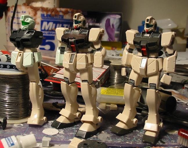
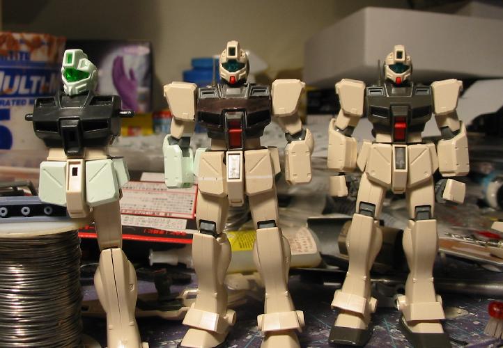
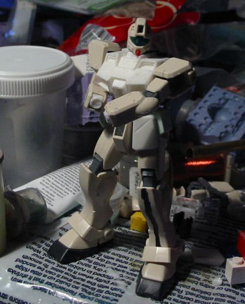
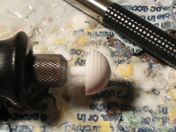
All the best material I’ve read on scratchbuilding emphasizes the creation of detailed plans as a first step. If a plan is good enough to give you the contour and measurements of any section of a part, then there is no reason why a detailed replica cannot be sculpted. In other modeling genres, creating the plans may be a matter of obtaining the right photos of the original subject and interpreting the perspective of the photos to create measurements. In this case, the original subject is a drawing whose perspective is apparently flawed, and whose subject is apparently inconsistently rendered. And yet, the original lineart for the subject defines the shape well enough that I can identify it. It has a form. It has characteristics which define subtleties in that form which distinguish it from other, similar forms. My goal is to represent that form as well as I can.

Ortho front #1
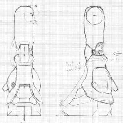
This is the first orthographic rendering I made of the Zaku Kai. Much of it is the result of taking measurements of the front-view lineart of the Zaku Kai, printed to 1:100 scale on metric graph paper. Some measurements and shapes I had to work out myself, whether because of difficulty interpreting the perspective of the lineart, or because of contradictions in the lineart. The result is a flawed sketch, done freehand on graph paper. Anything which isn’t aligned to the perpendiculars is skewed. And yet, it’s the first time I feel I’ve really drawn the Zaku Kai as it ought to look. I’ve since attempted to create new front-view renderings, experimenting with different measurements and shapes for some of the parts, but as yet I’ve been unable to come up with anything that I feel works as well as this rendering.
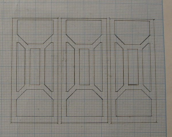
Chest

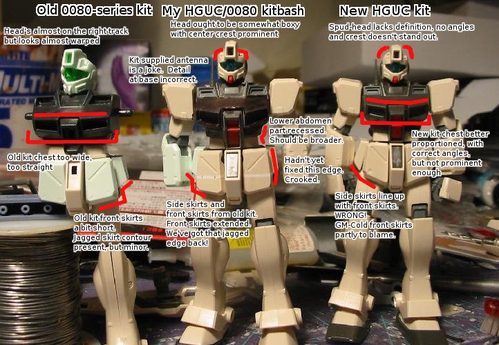
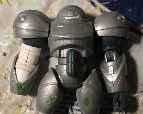
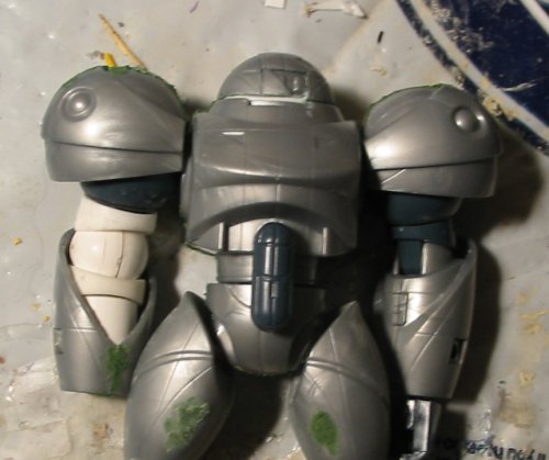
The chest is one of my favorite areas of the Zaku Kai design. I think it’s one of the design’s most distinctive features and also one of the points that’s most frequently gone wrong in model renditions of the subject. In addition to direct observations and measurements from the lineart, I based the design on some guiding principles; it’s hard to call them “observations” because they are subject to being contradicted in animation or sometimes in the reference lineart. But these are the things that I believe to be true regarding this design, and which I wanted to guide my rendition.

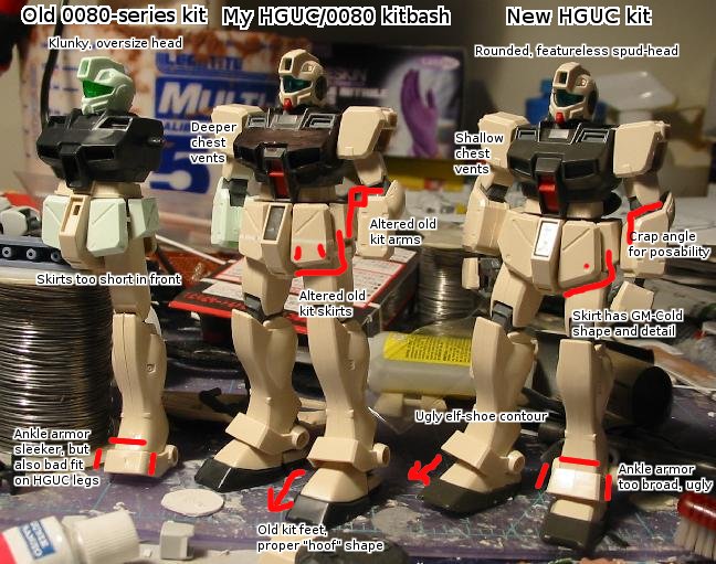
  • The chest block is not as wide or squat as it is often portrayed. I believe this to be a way people misunderstand the design when they see it.
  • The chest segments (left, middle, right) are about the same width.
  • The upper contour of the shoulder armor and the chest block defines a curve, concave upward. The tops of the left and right sides of the chest block, therefore, are not parallel to each other.

Using those assumptions as guidelines I turned the measurements from the lineart into a plan for the chest block which may well survive to the final version of the model. The main problem area for me at this point is the center area of the chest. Because the top and bottom of the chest block angles upward going toward the arms, I felt that the “vertical” lines defining the sides of the segments might be better off angled as well. I can’t really support that with observations from the lineart, though it’s pretty common in model renditions. I think it’s a good look. The problem is that since the sides of the center segment aren’t parallel, the bottom end is significantly wider than the top. This makes the construction of the cockpit area and the operation of its hinged door (even if that’s only supposed and not implemented) problematic.
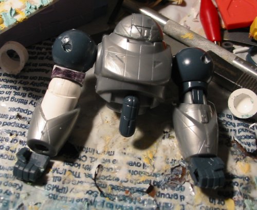
Arms

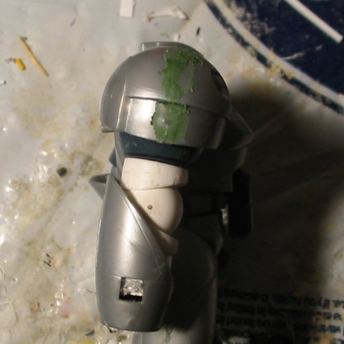
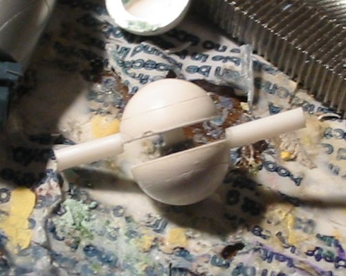
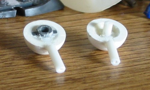
Much of the arms is simply my best rendering of the design from the lineart, mixed with an attempt to keep things a reasonable size, and tie the design to that of the original Zaku in terms of how it’s constructed. The upper arms were a bit hard to nail down, so in my rendering they’re a combination of the shapes I can see in the lineart with human musculature – “biceps” and “triceps” represented in armor shape. Around where the “deltoid” would be is an interesting feature of the original design, the sort which usually makes faithful model representations difficult. On my drawing you can see a rounded tab connecting the shoulder to the upper arm part. Because of how this bit is connected to the upper arm, it must turn with the upper arm as the arm turns. But the lineart doesn’t really show what any of that is connected to. For my rendition I decided that the shoulder underneath the armor would be spherical. This is common in some of Izubuchi’s other designs, such as the Nu Gundam. The upper arm and the “deltoid” tab then form a hollow sphere-shaped cuff which slides around the outer surface of the shoulder sphere. The main problem with this design in terms of posability is that it limits how far the arm can swivel outward according to the point where that tab hits the strut connecting the shoulder to the chest. Another complication is that the shoulder armor on the right shoulder needs to fit on top of the sphere and leave enough room for the arm to move around. I’ve tried to make it a size and shape I’m happy with, though it is inevitably a compromise.
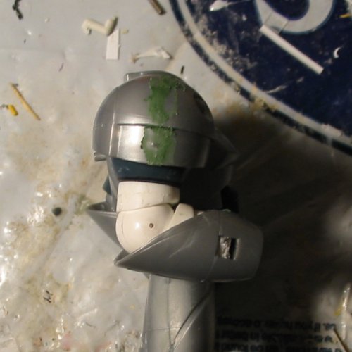
The Head

The head of the Zaku Kai is unusually small among Gundam subjects. It is also distinctive, and helps to create the look of a massive, bulky machine on a frame only marginally larger than the original Zaku. My observations of the Gundam 0080 anime and of the Zaku Kai lineart suggest that the head itself is about the width of the middle part of the chest block, and so I made my head only slightly wider than the top part of that segment. There are times when I look at the lineart and the head looks too small, and other times when I look at it and it seems absolutely perfect. I think in the end it’ll remain as it is.

Legs

The legs are the absolute worst part of this drawing. Inconsistent, skewed, and generally sloppy. (It should also be noted that I drew the left leg first, then drew the right leg, incorporating different ideas and changing some details – I then did some work to reconcile the two versions, but that effort wasn’t worth completing.) I found it easier to refine the design for the legs as a separate drawing. However, the intiial rendering here established a few design directions I want to pursue.

  1. The “standard pose” for the leg is angled outward, a stance near shoulder-width (whatever that means on a Gundam-style robot design…)
  2. The bottom “fringe” armor around the ankle is approximately parallel to the ground in this pose – the bottom edge of the fringe is not perpendicular to the center line of the leg, and the leg is not left/right symmetrical.
  3. I am considering adding a slight tilt to the foot, either as a posable joint or as a static feature of the sculpt. This will help the ankle joint to sit comfortably in its typical poses.

Summary

This drawing was a good start to this project, and is still the basis for composites generated on the computer using this lineart in combination with updated drawings for the legs. It was my initial codification (and disambiguation) of measurements from the lineart and likely most of it will survive to the final versions of the design.

New Elbow Joints

The Otakon deadline has come and gone, of course, and Patcon is coming up, most likely to zoom by me before I can finish this project. I’ve decided that I’m not entirely happy with the original elbow joints that I made (though I think they were nice work, and it’s great to see how simply something like that can be accomplished – I just really feel the precision on my projects ought to be better than that.) so I’m working on new ones (to be recast) using the last two 14mm hemispheres I have on hand. I have ordered more hemispheres, but with a little luck I ought to be able to get by with what I’ve got.

The big change in this effort is that I’m now using the Dremel as a way to check the alignment of the hemisphere relative to the rod, and to correct it. My first attempt with this technique involved mounting the hemisphere on the rod, then chucking it into the Dremel and sanding it down until it was centered. This reduced the diameter of the part from 14mm to 13mm, and I’m concerned about the resulting part’s uniformity as a sphere. But this part is very far along at this point – I scribed lines in it by holding a razor saw to it as it spun, and I puttied some minor mistakes and primed it to check the surface – it needs some more work but if I decide to move forward with it, it’s nearly ready.

My second (and last, until I get that order of hemisphere parts) attempt at this was done by first sandwiching 3mm worth of plastic plate, drilling a hole in it, and mounting that to the rod. Then it was chucked into the Dremel and sanded down until it fit inside one of the hemisphere parts. From there, the hemisphere part was carefully aligned on top of the shaped styrene. Alignment was checked using a pencil touched to the hemisphere while it was spinning. (If the hemisphere was off-axis, the pencil would make contact with just one side of the hemisphere. If the hemisphere was on-axis, the pencil would make a complete circle around the part, or close to it, and that circle could be checked to ensure it was parallel to the edge of the hemisphere.) Minor alignment issues were corrected by sanding the outside of the hemisphere as it was spinning. I think with a little luck this version of the part will work out nicely.

My plan is to complete this hemisphere-on-a-stick part and scribe two lines in it on the Dremel – one about 20 degrees from the planar side and one about 20 degrees from the axis – the idea being that for different projects I could fill in these lines or take advantage of them, as needed. Then the part will be recast, and the castings will be performed in different ways in order to create both the male part and the female part of the hinge from the same mold. If the first mold works out, then I’d like to alter some of the cast parts from the mold to pursue my 3-part hinge idea.
13mm part (primed)New elbow part starting pointSpin-sanded disc on a stickNew elbow part (current state, with pencil lines)

More Arm Work

After an emergency trip to the art supply store in Cambridge to get more mold rubber, I recast the cuff part for the upper arm and rigged up a simple test-shot of how the assembled arm will look, and comparing it to the original parts. Hopefully the results speak for themselves. In addition to being closer to the look of the original design, I also feel this joint looks better than the kit parts.

The reality of the deadline is looming. I’ve begun the process of sanding smooth the putty but it’s tough to say whether I’ll finish it before the con.
Arm Test ShotArm Test Shot (2)New arm (straight, side)New arm (flexed)

Arm Work

Creating a pair of spherical hinges took about two hours work. They’re just slightly misaligned, which is unfortunate, but I don’t think it’ll be a big deal for this first Sumo. I also took another four hours to create a new uper arm cuff which I’ll recast to create upper arm and forearm parts.

In the photos you can see basically how the new elbow hinges go together (if you look closely you can see the 3mm rod and polycap inside – when the hinge halves are pressed together, the joint appears as a solid sphere.) and roughly how the whole thing will look when completed. The modified hand part is also in the “Arm Progress” photo. The arm cuff took some time because I wanted it to look good for recasting, and to be convenient to fit onto kit parts with just minor alterations. Plus I was working with Bondo instead of my usual, preferred Doro Doro poly putty…. Don’t get me wrong, Bondo’s great for some stuff – Bawoo’s done incredible stuff with it and I’ve done some reasonably good work with it, too – but in some ways it just can’t compete with Doro Doro. There simply is no comparison. Now I’m off to make the mold to recast the upper arm cuff… (Mold preparation takes a lot of time, since the rubber needs to cure, so it’s not something that can be delayed at this point!)
Arm ProgressHinge ConstructionHinge Construction (2)

Rifle Troubles

As I’ve progressed through the painting of this project all kinds of stupid problems have cropped up. Masks lifting up and getting painted under, paint chipping, all kinds of bad surface scratches cropping up, etc. Really, some parts of this model are a real mess. But whatcha gonna do? Put another 100 hours into fixing the stupid thing? Nah, I’m ready to move on. But I’m finally in the home stretch, for real. Everything’s glossed, and I’m about to put the decals on it. It should be a lot of fun. One of the last big efforts I put into the paintjob was the rifles: All my other projects, the guns were just a one-color paintjob. This time around I wanted to use a few different colors to play with the details of the weapons. I messed up the surface here and there, cutting too deep with the knife when cutting the masking tape, but I think the overall effect is good. Then I lifted the liquid mask off the already-green camera eyes and… well, you’ll see. It was a mess, so I decided rather than masking and painting those stupid cameras again (which I’d never really managed to get properly smooth in the first place) I’d just replace them with cut rectangular pieces of clear plastic, and paint the back-faces of these fluorescent green. It’s something I picked up from Fichtenfoo’s Website. I didn’t try it before because I’m generally not so good with the precision shape-cutting, but in retrospect is really is easier most of the time than other methods.

Rifles (painted)Argh!New camera eyesMore new camera eyesRifle (paint patched up)Rifle overviewRifles (new camera eyes installed!)

Shield Widening

I decided that the previous attempt at a shield back-face wasn’t good enough. I feel like there were little sloppy areas here and there, and the mystery of what happened to require me to rearrange everything still bothers me. So I decided this time to make the detail by cutting it out of multiple thin layers. This time around I also refined the pattern a bit, rounding the corners to 45 degree angles and adding detail to the bottom layer.

I think this approach has advantages over the other ways I’ve attempted: it’s much easier to cut through a .3mm sheet rather than a 1mm sheet, and it’s easier to get things lined up properly when the guide is directly attached to the plastic. Plus this time around I drew the guides in pencil, rather than pen, and this gave me finer lines. It was actually pretty easy to get the cuts to be rather good, too – using a ruler as a guide to make the straight cuts, there were only minor variances which, in theory, will cancel each other out when the layers are joined.

I still need to clean up the parts a bit, but I think this will work out nicely in the end.

New shield patternsCutouts for back-side detailCurrent state of shieldComparison with kit shield and previous attempt at detailing widened shield.

More Painting

Most of the parts are painted now and just awaiting clear coating. The rifle had been painted navy blue – in past projects I’ve had a tendency to paint rifles and such in a single (usually metallic or grayish) color – for this project I decided I wanted to put a little more into it, so I decided to mask off most of the weapon and paint the little panel rectangles in a slightly different color – then later I’ll do a few more details in metallic black.

Rifles (masked)V-Fin (completed)Parts (1)Parts (2)