By tetsujin on 2007-01-18 | In Models | No Comments »
Tags: 1:100 Zaku Kai, chest construction
As mentioned previously, after I’d built my first attempt at the chest block part I realized that the plans I used to do it were incomplete – lacking in a couple features that had already been incorporated into the design plans, and a few of the angles had changed somewhat between that design and the current one. The process of creating the templates I used for the paper chest was fairly labor-intensive, as well: I did it by breaking up the chest design into triangles, calculating edge lengths, and putting triangles on graph paper with those edge lengths. The resulting “unfolded mesh” was adequately precise for its purpose but it had too many flaws to be used for a final part. So this time around I started with my Blender model, and used the “unfolder” script to turn a simplified version of the chest block into a template for building the part from styrene. As before, I used 1mm plastic sheet for the construction, and cut mitred edges where segments were to join.
The process yielded a much better template, and so the parts went together with fewer gaps and better consistency between the two sides. However, after finishing construction of the part I discovered that something in the process was adding length to the dimensions of the chest block: it could be that I didn’t cut the parts out quite right but I think mostly it was a problem with the mitre joins. They weren’t cut quite carefully enough and so they’re not precise: I’ve added about 1mm to the width of each chest half and other dimensions have grown around a half-milimeter. I’ll likely just sand down the excess volume to solve the problem. In the future I’ll probably use thinner plastic for the assembly, and possibly account for this error in my part templates, as well.
After the basic block was done, I created guides to help in the placement of the shoulder joints and cut holes for them. I also cut out the recess in the back where the backpack will sit, though I seem to have cut it wider than it ought to be. The opening in the back will be filled with poly putty later on in order to get a good fit for the backpack.
In the views showing the back and underside of the new chest block, it is the segment marked “G” that wasn’t represented in the previous attempt at building the chest block. Rather, plates F and H simply met at an edge at the bottom of the chest block. Additionally, the “H” plates were parallel to each other in the previous chest block attempt, where now they are angled, so that the areas nearest the middle of the body extend farther back.


By tetsujin on 2006-11-29 | In Models | No Comments »
Tags: 1:100 Zaku Kai, head construction
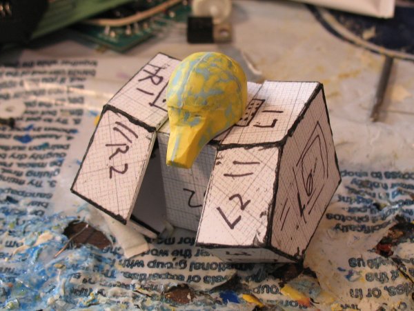
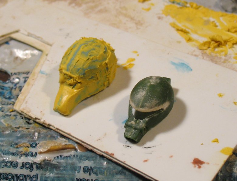
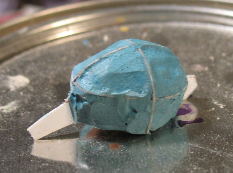
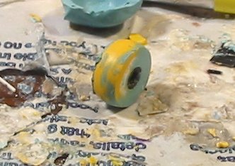
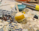
Pressing onward: I drew out the bottom-view of the head so I could create a styrene template from it and glue it to the bottom of the head work-in-progress. This makes it easier to establish the contour and edge of the bottom of the head and also to create the snout (and to ensure that it’s reasonably well-centered, too). I then used more poly putty to fill in the contours, both for the head and the snout. At this point I decided that I’d gone as far as I could usefully go with Bondo, so I switched to Mori Mori. I can’t find my Mori Mori catalyst at the moment so I used Doro Doro catalyst (I have plenty of that since every time I buy a can of Doro Doro it goes bad before I use it all up…) So far it hasn’t hardened up fully, but I expect it will in a few hours. Just for kicks, I included an old, modified 1:144 Zaku Kai head that I made about four or five years ago in the picture – comparison, if you like.

By tetsujin on 2006-11-29 | In Models | No Comments »
Tags: 1:100 Zaku Kai, Plans
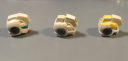
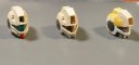
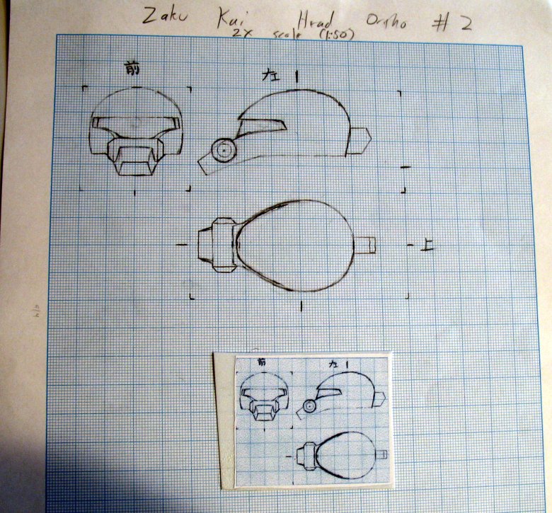
This is a rendering of the head that I made in order to clean up inconsistencies in previous head designs appearing in orthographic designs for the whole Zaku in preparation for building the actual head part. I had done one of these before, but I decided to make a new one in order to incorporate changes I’d made experimentally while creating the Blender model. The main difference is that v2 is two milimeters longer from the end of the snout to the back of the head than v1 was: otherwise the two head designs are pretty much the same.

Summary
This is, in a sense, the first “final” design in the project, in the sense that it’s a design I drew up and then immediately used to build a part. Other plans have been done with the expectation of further review and revision. My designs for the head have varied a bit in the different places where I’ve drawn it, as I tried to capture various aspects that I thought I saw in the lineart. The end result is a little more “moderate”, perhaps, than my initial impressions of the design – slightly less sleek and less pronounced in certain features, somewhat closer to the “standard” Zaku head proportions – and there are times when I wonder if I should’ve tried to make the head’s features more distinctive and pronounced. However, looking at the best references I have for the head I think my design is very much in line with how the head is represented in those references. At worst, perhaps, I think my design may be a bit too rounded at the middle and back of the head – perhaps meaning the head is not long enough front-to-back. The Zaku Kai head minimizes the impression of width with its length, and if I start to feel that the “egg shape” of the head’s top view is too pronounced, I may lengthen the head later to compensate.
By tetsujin on 2006-06-06 | In Models | No Comments »
Tags: 1:100 Zaku Kai, Plans
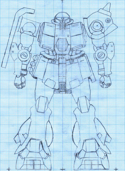
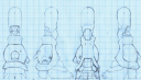
This front view is mostly a combination of Ortho Front #1 and Leg v5 redrawn on a light table. This front-view also incorporates various improvements and additions that were made on the computer composites, like the second arm, the shield, etc. I created it in order to have a solid baseline for creating side and rear views of the Zaku.The back view started as a trace of the front view in reverse – but the details for the rear of the leg were traced in, and I took a crack at defining the measurements for the rear skirts and backpack.
More recently, I’ve added a side view which is now included on this page. All three views will likely be revised as I find things which need refinement.


Summary
One of the constant challenges in this project is that what looks good from one angle doesn’t necessarily look good from another. I think the inclusion of the rear view went pretty smoothly all things considered. It always takes some experimentation to find the best way to arrange a part of the design that hasn’t been boiled down into measurements yet. Having the rear view in as good shape as it is makes me feel good about the state of this project, and I feel I can look forward to the point when all these plans will be done, and I’ll get started building. I think the V5 leg realy shines in these plans. All my previous hand-drawn full views have had poorly-traced renderings of inferior (and now obsolete) versions of my leg design… the rough, crooked lines of those legs really detracted from the whole, just as all the little sloppy bits of the drawing did. The new renderings have their rough ares, to be sure, but I feel it’s a big improvement in terms of clarity.
Somewhere in between the original ortho #1 and this rendering, the contour of the chest block changed: the top corners moved inward by 1mm. I’m not sure if this was intentional or if it was an error introduced somewhere along the way. As far as I can tell the change originated in my first three-view rendering of the chest block. I’m not entirely sure if the change should stay, but right now I’m inclined to keep it, as it makes the body look more dynamic. The original placement of that top corner made the chest look more rectangular, and possibly a bit too rigid.
It’s possible that this design change was an effort to prevent the bulk of the chest from overwhelming the head: there has been some discussion about whether the head might have been too small in my original rendering. My feeling has always been that the head was just as it should be and that perhaps adjusting the surrounding areas to improve the balance might be the way to go. So I think I may have been attempting that in this rendering. Based on the drawings I think the chest might be too sleek – but based on the physical prototype I made from this plan, I think it’s actually about right.
By tetsujin on 2006-04-29 | In Models | No Comments »
Tags: 1:144 Sumo
In the last update I described work on a three-part hinge that was to start with the use of the drill press to drill a hole through a block of styrene, perpendicular to the bottom face of the block, and use this as the core segment of the hinge. This was the basis of my most recent prototype for the hinge. What I found early on, however, was that the two faces of the block were not parallel due to variances in how I stacked the styrene sheets to create the block, and I had various difficulties in creating the remainder of the hinge. This frustrated me for a while, and I began to consider other ways of making the hinge part, including recasting a 14mm ball bearing and attempting to drill through its center, then cut it up to produce the hinge. I did a couple trials, and found that the process was far too error-prone with the equipment I have, and all the approach’s merits depend on being able to get it right the first time. In contrast, my other techniques have all allowed for initial imprecision, by emphasizing stepwise refinement.
I recently returned to the prototype I’d made with the help of my drill press, and refined my method to improve the work. Earlier work had all been done with a styrene rod as the joint’s axis, when testing or spin-sanding the joint. I found a supplier for a 3mm steel rod to do those jobs: in comparison the styrene rod was a bit undersized (meaning it wouldn’t totally fill a 3mm hole, meaning the parts would wobble) and it was flexible – meaning my precision was limited and my ability to detect precision problems was compromised. The steel rod solved those problems. I also began using the drill press to spin the parts both for sanding the sphere to spherical shape, and for sanding the planes flat and perpendicular to the axis. This combination made it easy to make a lot of progress quickly, and now I feel I have a prototype that is nearly ready for recasting.
I had debated on whether or not to create the counter-sunk areas where the outer hinge parts overlap the inner hinge parts before recasting what I’d built so far – I was concerned about the risk of destroying the work I’d done so far in the attempt to improve upon it. Ultimately, I decided to go for it, and so today I added the overlap between the hinge parts.
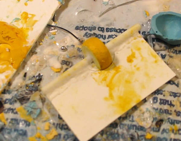
As for the joint’s current state: I think it may have a slight wobble relative to the axis but if so it’s minor enough that I’m willing to accept it. There are also minor problems with the planes where the hinge segments meet: as the hinge is turned the distance between the segments changes a little. But at all times there’s a gap there, so the variation isn’t as bad as it’d be as if the gap closed and opened as the joint was turned. The joint end cap was originally made with a hole all the way through it, and I’ve just started capping that hole so the entire outer surface will be spherical in form – that’s a bit rough still. The whole joint is a bit rough in places, in fact, as a result of various poly putty work I’ve been doing, little bits of poly putty have wound up on the joint surface. That’ll be relatively easy to correct. Also note that the pictures show an outer hinge segment on the end of the rod, an inner hinge segment next to it, and another outer hinge segment strung onto the rod: the second hinge segment is relatively crude because I stopped development on it. I had been working on all three parts but at a certain point I decided I had to choose which of the two would be recast (as they’re not identical, and the outer hinge parts should be identical.) It’s in the photos mostly just to show how the final joint will look. Obviously there’s still a lot of cleanup to do – the joint is going to be painted in Alclad Chrome, so all these little pits and bumps have got to go.


By tetsujin on 2006-03-25 | In Models | No Comments »
Tags: 1:100 Zaku Kai, Plans
Version 4 of my leg design looked good to me until I tried it in a composite with the rest of the Zaku body. All such composites that I do have the leg tilted, because I regard this as the Zaku’s “neutral” pose. But it’s much easier to take advantage of the graph paper when drawing the leg if the leg is aligned to the graph lines – so I designed the leg in one pose and then found it didn’t work so well in the pose I wanted it to look good in. One day at work I took one of my paper printouts of the V4 composite and altered it with whiteout and a pen in order to get the look I wanted. I was able to get a significant change in effect without a huge change to the leg: I raised all of the leg apart from the bottom edge of the ankle skirt, and I moved the inboard pod’s lower edge a little bit up and inward. These changes were the basis for version five of my Zaku leg design.
Version 5 is also the first version in which I’ve drawn the leg from front, back, and both side views. Integrating the back view was tougher than I’d expected – the two major issues were that the ankle skirt/fringe thing, which looks fine from the other views, looks like it doesn’t come down far enough in the rear view. Second is that the lower legs look too stout from behind. In front they have the center part of the lower leg breaking up that space, but in back the pod is uninterrupted, and it’s additionally compressed a bit above and below. I did some give-and-take trying to improve the look of the back of the leg, I’m pretty happy with it now.
Key features of this version of the design:
- My first rendering of the rear side of the leg.
- Closest yet to my initial front-view sketches
- Lower edges of leg pods moved upward and inward toward center of leg to accentuate the inward curve at the bottom of the pod.
By tetsujin on 2006-01-26 | In Models | No Comments »
Tags: 1:144 Sumo
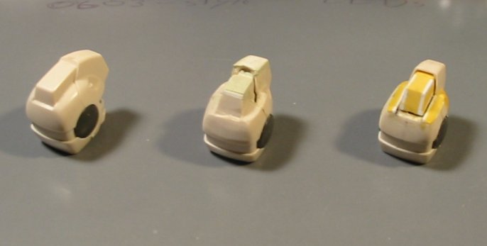
Since the last update I’ve abandoned the idea of creating a two-part spherical hinge for the elbow in favor of a three-part hinge. I could explain the design but I find pictures communicate these ideas better, so there’s a mockup photo to see. Just picture the middle part attached to the model’s shoulder, and the two outer parts pinned to the forearm. The middle part rotates about the axis and that’s the hinge action.
I had a lot of false-starts on this effort. My first attempts involved creating the outer parts first – I trimmed down one of my plastic hemispheres (from the full 7mm radius thickness to 4mm) and attempted to mount that, perfectly centered, onto a strut. When that didn’t work out, I tried spin-sanding it on the dremel (and then building the part back up again with poly-putty, and repeating) in the hopes of making the part more symmetrical about the axis. I think the (styrene) axis I’d mounted it on was a problem, though, subject to flexion. I got as far as mastering the part this way and recasting it, but now I’m not sure if I’ll be able to use those castings.
From there I tried to use two of the castings to create the middle segment – I had all kinds of problems trying to do different poly putty casting maneuvers (many of which wound up stuck to the pattern rather than the part) and ultimately I wasn’t happy with the results. This work went through the same process of spin-sanding and re-puttying as well, but I ultimately gave up on that approach.
My current approach is to build the middle segment first. I started by cutting twelve circles of .5mm styrene and stacking them into a cylinder. I used my new drill press (best Christmas present ever!) to drill a hole down the middle of the cylinder, and I created a turning template with which I’m attempting to form the spherical surface of the part. Once that is done I’ll either re-use the end part I’ve already cast, or I’ll make a new one.
The work so far is promising – more successful, I’d say, than my earlier attempts at using similar template-turning to create spheres. I think my template this time around is more precise, thanks to my circle-cutter and a slight bit more patience. However, there are still other problems. Mainly, the flat surfaces of the middle hinge part still aren’t quite completely planar and perpendicular to the axis. However, I have a plan to correct this. I’ll start with a thick plate – something I’m confident has parallel and planar upper and lower surfaces, and I’ll drill a hole in it with the drill press, and install a 3mm rod in it. Then I’ll apply putty to the hinge part and slide it down the rod until it comes in contact with the plate. The result should be a planar surface of poly putty perpendicular to the axis applied to the hinge part. This depends on the precision of my drill press and the straightness of the rod I use – both of which I’m reasonably confident in.


By tetsujin on 2006-01-25 | In Models | No Comments »
Tags: 1:144 Z'Gok Diorama
While I did get a lot of things done on the GMs before the original Otakon 2004 deadline, one thing I had failed to accomplish was to correct the spud-head. I took some time to try to determine where exactly the kit head went wrong, and in what ways it could be a useful part, and came to the conclusion that the main camera housing and the front part of the crest were mostly correct, but everything around them was wrong. In particular, the back end of the head’s crest is misshapen, and the top surface of the head surrounding the crest is far too high, with the end result that the crest is largely lost – as though the entire head were over-inflated, losing its distinctive details in the process. So the plan for the head was as follows:
- Cut off the back part of the crest and the top surface of the head.
- Build a new back part for the crest, using the lineart as a guide, and install it.
- Build the back of the head back up around the crest. Augment or reduce other areas of the head as necessary. (The temples, around the vulcan cannons are the main area in need of such attention.)
- Cut out the badly molded-in cheek vents, so that Kotobukiya rectangular nozzles may be inserted as substitutes.
- Create camera details and a new, vacuum-formed visor.
- Recast
- Type question-marks followed by obligatory underpants gnomes reference.
I think I originally had four HGUC GM Command kits to work with, out of which I needed to make three GMs. Through experimentation (and, consequently, failure) in attempting to refine the head, I eventually destroyed three of the four heads, and kept the fourth in reserve as a reference for how the kit head looks unaltered. (One was used in an attempt to make the eye visor area larger – a plan I later abandoned. One was used in an attempt to augment the existing crest parts and cut down the rest – abandoned because it was too difficult to get things level and aligned. The third is my current work-in-progress head, but the jaw part was damaged during alterations so I got a fifth in the form of a space-type HGUC GM Command kit, and got a replacement jaw from there.)So far, I’ve created the new head crest and sculpted the back of the head – though it still needs refinement and correction in places where it’s no longer symmetrical. I have created a prototype for the “monoeye” inside the head and begun the process of re-sculpting the vulcan cannon areas. I’ve cut-out the openings for the rectangular nozzles to be installed at the jaw line (mutton-chop thrusters??) but not installed the nozzles yet.