By tetsujin on 2008-01-01 | In Models | No Comments »
Tags: sockmonkey, sockmonkey sandrock
I cut the head apart – took the whole beard off the face and replaced it with Kotobukiya parts and Aves, cut the top of the helmet off and made it narrower and shorter (vertically). This all took a couple hours but I feel like it’s already made a big difference in the appearance of the model.


By tetsujin on 2007-11-28 | In Models | No Comments »
Tags: 1:100 Zaku Kai, Backpack
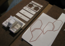
I started a second version of the backpack based on the new construction plans: however, careless work introduced a few visible errors, so I decided to start again, and be more careful in the new attempt. Particularly, I want to be very sure that matching parts for the left and right sides match as closely as possible, that all 90 degree joins really are at 90 degrees, etc. It makes progress go a little more slowly, but I am learning that it’s still faster than scrapping a part and starting over again.
Most of the work so far has gone into the center thruster housing of the backpack: the plates are the same design as those used in the previous attempt, but this time I glued them to each other before doing the final edge-sanding, to help make the two parts match up better, and then cut them apart again for assembly. I added additional plates perpendicular to the side plates in order to help lend the part a stronger structure and a more consistent spacing, and I squared up the major joins as I made them. Some bits of precision were still a matter of eyeballing the part, hopefully that will be good enough. In order to position the part within the rest of the backpack, I added another couple of spacer plates to the interior of the structure, to help ensure that the thruster housing winds up in its proper place in the end.
One fairly major problem I had with the second attempt was the side plates of the backpack: I designed them out of .5mm plate so each plate could be made of two layers stacked: in this way I hoped to create the part’s mitred edge as part of the plate layout… However, small mistakes in cutting the plates resulted in parts that didn’t match up well enough to create a consistent mitred edge… So this is another bit of the backpack I’ll have to do more carefully this time.
By tetsujin on 2007-11-09 | In Models | No Comments »
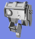
Tags: 1:72 Armored Core CR-C75 "Hakuheisen"
I’ve been doing more work on this project, hollowing out shallow-molded details like the open end of the grenade launcher barrel and starting the long road of assembly and cleanup work needed to get this thing ready to paint.
Right now I’ve started with the weapons: the GAST rifle, the grenade launcher, the missile interceptors, and the laser blade: I’m working on getting those parts glue-assembled and ready for paint. So far the interceptors are done and the grenade launcher is shaping up pretty well. The rifle still needs some more work, and I haven’t started on the laser blade.
When I get more time I want to work some more on the wiring: I’ve come up with some ideas of how to run wires down through the legs to the leg thrusters and so on: it’s a bit complicated but I think it’ll work pretty well. It’s a bit daunting to think about it, though. :)
By tetsujin on 2007-11-04 | In Models | No Comments »
Tags: 1:100 Zaku Kai, Backpack
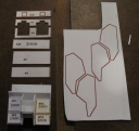
There were some issues with my previous attempt at building the backpack: some angles weren’t quite correct, some of the places where plates were joined inside the backpack were kind of sloppy (featuring gaps and, later, excessive filler) so I decided to start over using what I learned about box joins vs. mitre joins when I was building the chest block insert… In addition, I decided to lay out a more complete plan for how the parts would be constructed, and how exactly they should be shaped. Here are the results so far:
Key changes in this version are the use of box joins to attach plates wherever possible: there are very few mitre joins on this version. The other thing I’ve learned which I’ll be applying to the new part is that it’s easier to create clean right angles on plate edges by cutting the edges slightly oversized and then sanding them down… The quality of part edges was one of the more significant problems with my earlier build, so I’ll be pleased to improve on that this time around.
Additionally, I reorganized the internal construction a bit: One of my concerns with the first build was that the left and right thruster wells weren’t at the same angle. This time, two of the three plates that form the thruster well on each side will go all the way across, which should make it easier to ensure that the angles in those areas are consistent.
By tetsujin on 2007-10-03 | In Models | No Comments »
Tags: 1:72 Armored Core CR-C75 "Hakuheisen"
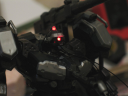
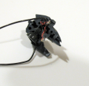
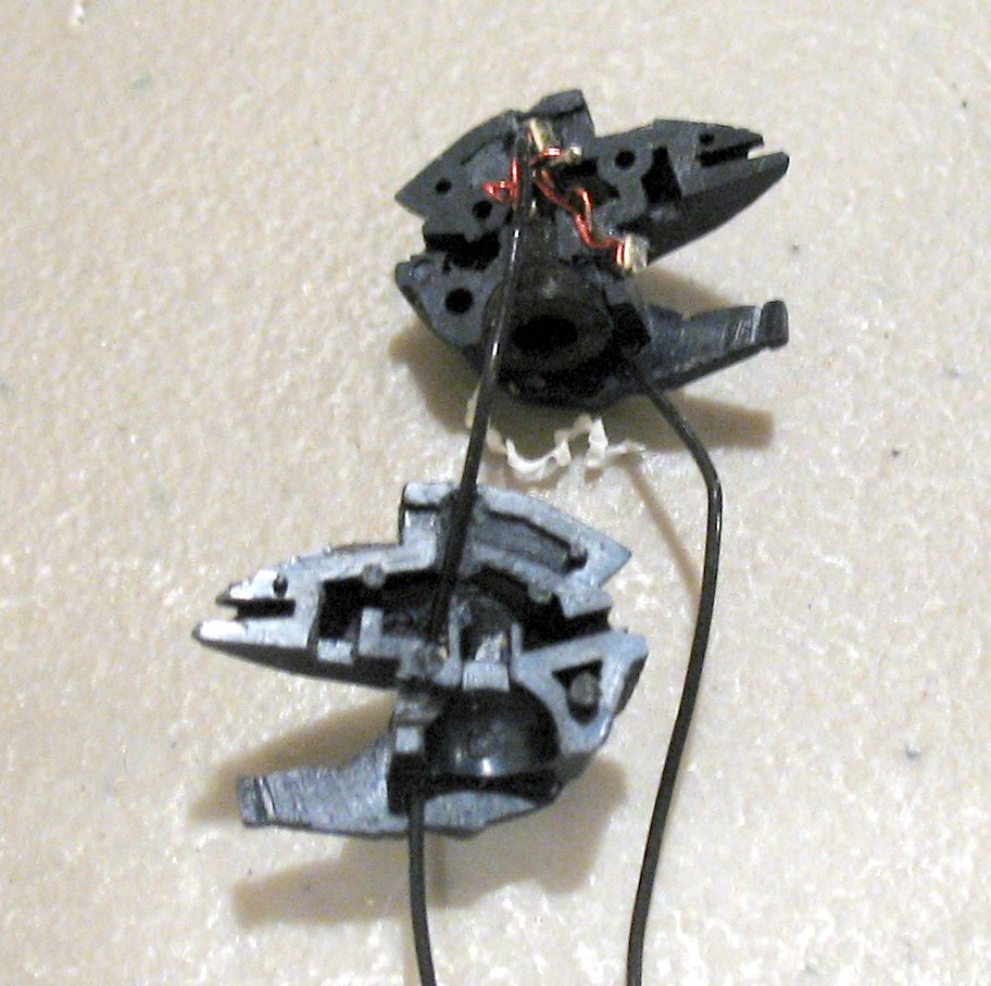
I decided early on that I wanted this kit to have LED lights, and so I’ve added some to the head already and am planning to add some to the thrusters. (The tough part of adding LEDs to the thrusters is that the thrusters are too shallow… So I had to hollow them out a bit.) I’ll light the back thrusters and the leg thrusters, and that’ll be it for LEDs. I had considered lighting every little camera eye on the thing, plus the weapons and the overboost, but I decided that would be too difficult. I want to keep this project relatively simple, but I also want the end result to be really cool… So I must find the proper balance.
The LEDs in the head are surface-mount LEDs, the 0603 type. They’re small enough to fit almost anywhere. They’re wired together with magnet wire from Radio Shack – it’s a type of wire that has insulation painted-on, which means it’s thinner than equivalent jacketed wire. They’re wired to the outside using 30 AWG stranded Teflon wire, which is my usual choice for wiring in model projects, as it’s quite thin and very resilient.

By tetsujin on 2007-06-09 | In Models | No Comments »
Tags: 1:100 Zaku Kai, head construction
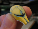
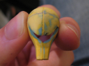
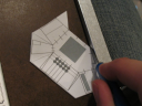
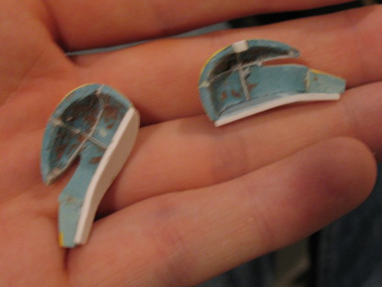
After earlier work I decided that the snout of the head part looked crooked. To solve the problem I split the head in half down the middle, to make it easier to take measurements relative to the center line. This was relatively easy because the part was built with a thin styrene plate on the center line. From there I improved the part a bit: it’s shaping up but I need to work out a way to effectively check the two sides against each other.
Splitting the part:

After Refinement
By tetsujin on 2007-06-09 | In Models | No Comments »
Tags: 1:100 Zaku Kai, chest construction
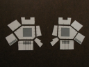
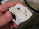
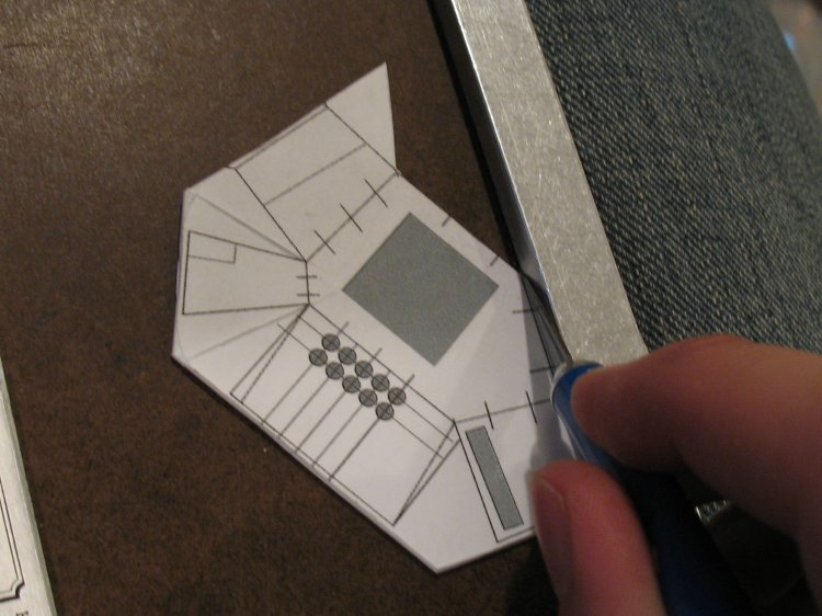
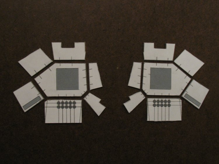
The third version of the chest block part had a few problems: in particular it was prone to warping and it didn’t have the holes on the bottom of the chest block drilled out, or even marked. As a result I decided to remake the chest block part from thicker stock, and drill out the holes before assembling the bottom plate to the rest of the chest block.
I got as far as assembling the left-side part for the fourth version of the chest block before I realized that the Blender mesh I was “unfolding” to produce the part template was crooked in places. To correct the problem, I started over with a new Blender mesh for the fifth version.
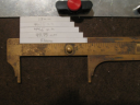
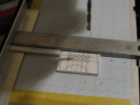
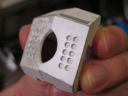
Drilling the holes – two rows of five holes, evenly spaced at 3.25mm between centers, proved to be a bit of a challenge. In the early attempts, I tried lining up the drill bit with the template markings on the part itself by eyeballing it, using a straight-edge guide to help the rows come out straighter. That proved difficult: with only .75 mm space between the holes, small errors were too easy to spot. To help make the drilling more precise, I cut a set of guides from styrene strip, to line up the part at the correct point along the drill press’s straight edge. The result was a noticably better set of holes.
Once the v5 parts were assembled, I used left-over plates that I’d cut out for the v4 parts to reinforce the inside of the v5 parts: 1mm thickness was enough to make a fairly strong part, but I felt that the parts would recast better if they were 2mm thick. The parts are not yet finished but at this point I’m confident that I won’t need to start over again.
Cutting and assembling the parts:
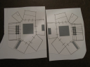
Drilling Guides:
Chest Parts, Assembled and Reinforced:
By tetsujin on 2007-05-15 | In Models | No Comments »
Tags: 1:100 Zaku Kai, head construction
Since the last update, the head has been through a few stages of refinement, in which the head was bulked up with poly putty and sanded down again. The head still needs work (in particular, I think the back end of it is a bit lopsided) but I am hoping a couple more refinement passes will smooth that out.
Overview:


Comparison with MG Zaku, MG Hi-Zack, and MG Zaku F2 heads:


